EP E
series
11-03
12
Illustrations may differ from the actual product
Allowing for printing errors and errors on proofs
Electronic control system - settings
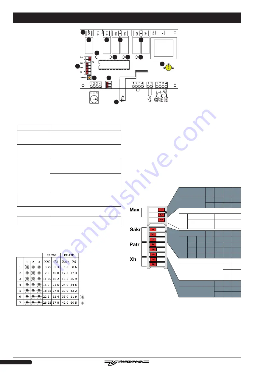
6. Power/status light.
Steady glow:
Normal operation.
One long
+
one short flash:
Power staging is limited by delayed
reconnection after a power cut.
One long
+
two short flashes:
Power staging is limited by the load guard,
the room thermostat or other external
control.
One long
+
three short
flashes:
A. Excess temperature: the power will be
reconnected when the temperature has
fallen.
B. Faulty temperature sensor: you must
replace the sensor before running the
boiler. To cancel the alarm, disconnect the
boiler for 10 seconds.
One long
+
four short flashes:
Remote control activated.
Rapid flashing
Bypassed delayed reconnection –
"SNABB" [FAST] button pressed.
Off:
No power (switch set to position O with
UTK E)
8. PCB.
The power is controlled with binary logic, which means that the
three power groups are connected as in the table below.
9. Indicator for power group one.
10. Indicator for power group two.
11. Indicator for power group three.
24. Temperature setting with remote control.
25. Switch for external block/remote control. See External block and
remote control, page 6.
26. Button to temporarily disable delayed reconnection after power
failure and to speed up the connection of power stages.
According to the standards, no more than 50% of the power can
be connected immediately after a loss of power lasting longer
than three minutes. The remaining power is delayed by an hour.
To test the boiler after it has been without power, for example
during installation or servicing, the delayed reconnection can
be disabled temporarily by pressing and holding the "SNABB"
[FAST] button until the status light stops flashing.
You can use the "SNABB" [FAST] to speed up the connection of
power stages for testing. Keep the button pressed for as long as
you need. The power may be limited by the load guard or by the
excess temperature protection.
27. Switch for setting operating parameters:
28. Relay outputs for power group one.
29. Relay outputs for power group two.
30. Relay outputs for power group three.
31. Output for circulation pump with summer mode/eco function
– the pump stops eight hours after the last time a power stage
is connected. The pump is operated briefly every twelve hours.
For best results, use UTK E to control the boiler. See point 27,
Circulation pump
Connected power group
Power group Power
Power
Current
Step
Non-connected power group
.
.
.
.
.
.
.
.
.
.
.
.
.
.
.
.
.
.
.
.
.
.
.
.
.
.
.
.
Current
OFF
↔
ON
The factory settings are shown in bold.
Number of power
stages
7
6
5
4
(1&2)
ON
ON OFF OFF
ON
OFF ON OFF
Cirkulation pump
(3)
OFF
ON
eco/summer
mode
continuous
operation
Main fuse
EP42
EP26
(1-3) 125A 100A
80A
63A
50A
35A
ON ON
OFF
OFF
OFF
OFF
OFF OFF
ON
ON
OFF
OFF
ON OFF
ON
OFF
ON
OFF
Stage size
EP26 EP42
(4 - 6)
ON ON
Do not change this
parameter
ON ON
OFF ON
Delayed reconnection
2h
1h
0h
(7 & 8)
ON
OFF
OFF
OFF
ON
OFF
24
25
28
29
30
31
8
9
10
11
6
27
26
6


