background image


POWXG3005 

EN


Copyright © 2014 VARO 

P a g e

 | 

6


www.varo.com 

ASSEMBLY 

The trimmer is supplied with some components which need to be assembled. Please 
proceed as follows: 

7.1 

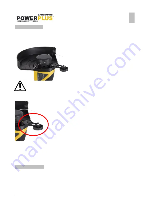
Safety guard assembly 


Insert the safety guard (11) onto the motor 
housing and secure it with 4 screws. 


Carfully peel off the tape overt he cutting 
blade (14) 

Warning:  the  guard  has  a  very  sharp  cutting  edge  on  1  side  for  cutting  the 
nylon line. 

7.2 

Wheel assembly 


Adjust the location of the safety guard and the wheel 
assembly. 


Be sure that the pillar of the safety guard can insert 
the hole of the wheel assembly. 


Then fix them firmly with 2 screws  by the driver. 

7.3 

Auxiliary handle assembly 


Adjust the location of the auxiliary handle and the locking base. 


Insert the locking knob and lock them firmly in a clockwise direction. 


If you want to adjust the angle of the auxiliary handle, loosen the locking knob counter 
clockwise, rotate the auxiliary handle as you want.  When it reach a proper location, lock 
the locking knob firmly in a clockwise direction again. 

OPERATION 

8.1 

Starting  


To switch on the trimmer first press the On/Off trigger (5). To switch off simply release the 
On/Off switch trigger(5)  


If you find that the nylon line is too short, let the trimmer run for a few seconds without 
touching the working area to allow the trimmer to cut the line after it lengthens. 


Do not overload the trimmer, cut in small sections which will greatly improve efficiency by 
keeping the trimmer running at high speed,  

Summary of Contents for POWERplus GardenPro POWXG3005

Page 1: ...4 5 5 Service 4 6 ADDITIONAL SAFETY RULES FOR GRASS TRIMMERS 5 7 ASSEMBLY 6 7 1 Safety guard assembly 6 7 2 Wheel assembly 6 7 3 Auxiliary handle assembly 6 8 OPERATION 6 8 1 Starting 6 8 2 Adjust the...

Page 2: ...base 9 Tube 10 Function collar telescopic 11 Safety guard 12 Adjust button cutting angle 13 Guiding wheel 14 Cutting blade 3 PACKAGE CONTENT LIST Remove all packaging materials Remove remaining packa...

Page 3: ...working area clean and well lit Untidy and dark areas can lead to accidents Do not operate power tools in potentially explosive surroundings for example in the presence of inflammable liquids gases o...

Page 4: ...evices for connecting dust extraction and collection facilities please ensure that they are attached and used correctly Using such devices can reduce dust related hazards 5 4 Power tool use and care D...

Page 5: ...e appliance remove sticks stones wire and other obstacles from the surface on which you intend to work Only use the appliance in an upright position with the cutting line pointing to the ground Never...

Page 6: ...liary handle assembly Adjust the location of the auxiliary handle and the locking base Insert the locking knob and lock them firmly in a clockwise direction If you want to adjust the angle of the auxi...

Page 7: ...make sure that the device is switched off and completely separated from the power mains For edging driveways and paths transform the trimmer from trimmer mode to edging mode as follows Push the adjust...

Page 8: ...ally wraps around the shaft and trimmer head assembly Cutting tall grass at ground level Cut tall grass from the top down Line trimmer stops and will not start again Unit failed Plug is damaged Contac...

Page 9: ...rised customer service centre for Powerplus tools You can always obtain more information at the number 00 32 3 292 92 90 Any transportation costs shall always be borne by the customer unless agreed ot...

Page 10: ...e essential requirements and other relevant provisions of the applicable European Directives based on the application of European harmonized standards Any unauthorized modification of the apparatus vo...

Reviews: