background image

1

Please


check


the


package


when


receiving


the


package

Before


installing


and


using


the


product

please


firstly


check


whether


the


appearance


of


the


product


is


intact


and


whether


the


variety


and


quantity


of


accessories


are


consistent


with


the


packing


list


in


the


user


manual

If


there


is


any


defect

please


contact


the


seller


or


manufacturer


in


time

.

Installation


and use


Installation


and


use

06

English

05 English

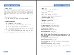
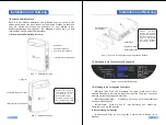
Operation panel

Oxygen outlet
Power connector

Radiator grille

Figure


1

Right


side


view

 – 

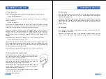
Figure


2

left


side


view

 – 

Note

It


is


normal


for


hot


air


to


be


discharged


from


the


heat


dissipation


vent

.


Make


sure


that


the


air


space


at


the


air


inlet


and


outlet


is


smooth

.

Note:


The


user


cannot


disassemble


without


p e r m i s s i o n

i f  

necessary

It


needs


to


be


returned


to


the


dealer


or


professional


for


processing

.

Attention:


User


is


not


allowed


to


open


this


part

.

Figure


3

S

chematic


d

iagram


o

f


i

nternal


b

attery


p

lacement

 – 

3

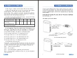
Introduction to operation panel function

2

Outline


diagram

1. Button function introduction


Power


button

Start


and


stop


keys

Short


press


the


button

the


machine


will


start


to


work;


long


press


the


button


for


3


seconds


during


work

the


machine


will


stop


working;


Grade

Adjust


output


oxygenflow


Time

Setting


device


using


time

adjustable


from


0~240


minutes

2. Display content introduction


Accumulated


hours

display


how


long


the


device


has


been


working


(

unit

hour

)

Figure 4

Operation panel diagram

 – 

Summary of Contents for NT-1

Page 1: ......

Page 2: ...29 Pr cautions de s curit 30 Pr sentation du produit 31 Param tre technique 32 Installation et utilisation 33 38 Pr cautions d emploi 39 Entretien et maintenance 40 D pannage 41 Liste de colisage 42...

Page 3: ...erature sparks and fire in the air To avoid accidents children are not allowed to operate the equipment alone When breathing oxygen do not wrap the hose around the neck The elderly who can t act easil...

Page 4: ...hnical Parameters 04 English 03 English 1 Model NT 1 2 Power supply AC 100 240V 50 60HZ DC 12 16 8V 3 Power 75 W 4 Built in battery capacity 92 WH 6 4 AH 5 Flow gear 1 5 gear 5 gears have the highest...

Page 5: ...ke sure that the air space at the air inlet and outlet is smooth Note The user cannot disassemble without p e r m i s s i o n i f necessary It needs to be returned to the dealer or professional for pr...

Page 6: ...s for reference only There are a total of four battery indicator lights on the operation panel 100 indicator light is on battery power 90 75 indicator light is on 90 battery power 75 50 indicator ligh...

Page 7: ...lly Requirement input terminal DC voltage is DC 12 16 8V current is 6A 4 2 Connect disposable oxygen inhaler Connect the flared end of the disposable oxygen inhaler tube firmly to the oxygen outlet of...

Page 8: ...the electrical schematic diagram of the product please contact the manufacturer or after sales service Use and Purchase Of Disposable Oxygen Inhaler 1 This equipment is a pulse oxygen supply mode To...

Page 9: ...hine malfunction Contact the seller Smell in Oxygen The oxygen inhaler has not been cleaned for a long time resulting in dirt in the tube Clean or replace in time oxygen tube The new oxygen inhaler wi...

Page 10: ...mgebung Hitze Funken offene Flammen usw gibt Um Unf lle zu vermeiden lassen Sie Kinder das Ger t nicht allein bedienen Wickeln Sie den Schlauch nicht um den Hals wenn Sie Sauerstoff einatmen lassen Si...

Page 11: ...der Maschine in Echtzeit informieren kann 1 NT 1 2 Stromversorgung AC 100 240V 50 60HZ DC 12 16 8V 3 Leistung 75 W 4 Eingebaute Batteriekapazit t 92 WH 6 4 AH 5 Durchflussmenge 1 5 St nde 5 h chste Du...

Page 12: ...utsch Tragegriff Lufteinlass des Kompressors Luftauslass zur W rmeabfuhr Hinweis Es ist den Nutzern nicht gestattet sie privat zu demontieren falls dies erforderlich ist muss an den H ndler oder einen...

Page 13: ...25 Anzeige leuchtet immer Batteriekapazit t 25 Kontrollleuchte und Alarmleuchte Alarmleuchte Diese Leuchte leuchtet immer dann auf wenn eine Anomalie im Betrieb des Ger ts festgestellt wird w hrend a...

Page 14: ...erstoffabsorber wie in der Abbildung gezeigt stellen Sie die Austritts ffnung auf eine geeignete Position ein und dr cken Sie den Befestigungsring nach oben um ihn nach dem Tragen zu fixieren Achten S...

Page 15: ...t IV Verwendung und Kauf eines Einweg Sauerstoffkonzentrators 1 Dieses Ger t ist Puls Sauerstoff Versorgung Methode verwenden Sie dieses Ger t muss der Sauerstoff Absorber Verwendung angeschlossen wer...

Page 16: ...Sauerstoffabsorber wurde lange Zeit nicht gereinigt was zu Verschmutzungen in der R hre f hrte Rechtzeitig reinigen oder durch eine neue ersetzen Sauerstoff Ansaugrohr Neue Sauerstoffabsorber k nnen z...

Page 17: ...nce de facteurs tels qu une temp rature lev e des tincelles et des flammes nues dans l environnement Pour viter les accidents veuillez ne pas laisser les enfants utiliser seuls l quipement Lorsque vou...

Page 18: ...duit Param tre technique 1 NT 1 2 Alimentation Courant alternatif CA 100 240V 50 60HZ Courant continu DC 12 16 8V 3 Puissance 75 W 4 Capacit de la batterie int gr e 92 WH 6 4 AH 5 Engrenage de d bit 1...

Page 19: ...sateur ne peut pas le d monter en priv Le cas ch ant renvoyez le au revendeur ou un professionnel pour limination Figure 3 Sch ma sch matique du placement de la batterie interne 3 Introduction la fonc...

Page 20: ...batterie 25 Voyant indicateur et voyant d alarme Voyant d alarme Ce voyant est toujours allum lorsqu une anomalie est d tect e pendant le fonctionnement de l quipement et le code d alarme correspondan...

Page 21: ...ant est de 6A 2 Connecter l inhalateur d oxyg ne jetable Connectez fermement l extr mit vas e de l inhalateur d oxyg ne jetable la sortie d oxyg ne de l appareil et portez l autre extr mit en vous r f...

Page 22: ...rend actuellement pas en charge l utilisation de batteries externes 4 L adaptateur secteur et le cordon d alimentation de la voiture partageront la m me prise de courant donc un seul d entre eux peut...

Page 23: ...xyg ne L inhalateur d oxyg ne n a pas t nettoy depuis longtemps ce qui entra ne de la salet dans le tube Nettoyez ou remplacez le nouveau tube d oxyg ne temps Le nouvel inhalateur d oxyg ne aura une l...

Page 24: ...GB9706 43 44...

Page 25: ...45 46 1 NT 1 2 CA 100 240V 50 60HZ DC 12 16 8V 3 75 W 4 92 WH 6 4 AH 5 1 5 5 6 93 3 7 58dB A 8 7 09 4 92 10 63 9 2 95 kg 10 II 11 12 13 50 F 95 F 30 75 860hPa 1060hPa 5 4 14 20 60 10 93 700hPa 1060hPa...

Page 26: ...47 48 1 2 3 1 3 2 4...

Page 27: ...49 50 10 5 5 ML 20 1 2 3 4 5 20 25 30 40 50 4 100 90 75 90 75 50 75 50 25 50 25 25 25 F0001 F0002 F0011 F0012 82 50 AC...

Page 28: ...52 1 AC AC AC AC AC AC 100 50 60Hz DC12 6A 2 51 3 4 3...

Page 29: ...54 1 2 3 4 AC 1 5 25 6 4 8 9 7 30CM 1 2 3 53 1 2 1 5 2 1 25...

Page 30: ...1 1 2 AC 1 3 AC 1 4 1 5 1 6 2 7 1 8 1 56 55...

Page 31: ...ctores como altas temperaturas chispas y llamas abiertas en el entorno Para evitar accidentes los ni os no pueden operar el dispositivo solo Al inhalar ox geno no envuelva la manguera alrededor del cu...

Page 32: ...tado de producci n de ox geno del dispositivo 1 NT 1 2 Poder Corriente alterna CA 100 240V 50 60HZ Corriente continua DC 12 16 8V 3 Potencia 75 W 4 Capacidad de la bater a incorporada 92 WH 6 4 AH 5 V...

Page 33: ...r a por s mismo sin permiso y si es necesario d e s m o n t a r d e b e devolverla al distribuidor o profesional para el desmontaje Figura 3 Diagrama Esquem tico de la Ubicaci n de la Bater a Incorpor...

Page 34: ...a 25 Luz indicadora y de alarma Luz de alarma Esta luz est siempre encendida cuando se detecta una anomal a durante el funcionamiento del dispositivo mientras se mostrar el c digo de alarma correspon...

Page 35: ...remo acampanado del inhalador de ox geno desechable a la salida de ox geno del dispositivo y col quese el otro extremo con referencia a la figura siguiente Col quese el inhalador de ox geno desechable...

Page 36: ...de poder a bordo de autom vil compartir n la misma toma de corriente por lo que solo se puede usar uno de ellos a la vez 5 Cuando la energ a de la bater a incorporada es inferior al 25 la luz indicado...

Page 37: ...empo lo que produce suciedad en la manguera La torre molecular dentro del dispositivo est bloqueada P ngase en contacto con el proveedor del dispositivo para una soluci n Existe un ligero sonido de es...

Page 38: ...amma aperta ecc Si fa divieto ai bambini di manipolare da solo il dispositivo al fine di evitare l incidente Nell inalare l ossigeno non avvolgere il tubo flessibile intorno al collo gli anziani incon...

Page 39: ...elle densit d ossigeno suggerisce in tempo reale la generazione d ossigeno della macchina 1 NT 1 2 Alimentazione 100 240Vac 50 60HZ 12 16 8Vac 3 Potenza 75 W 4 Capacit della batteria incorporata 92 WH...

Page 40: ...to di smontare discrezionalmente Qualora necessario rendere il prodotto al distributore od il personale professionale per trattamento Fig 3 Schema della messa della batteria incorporata III Introduzio...

Page 41: ...a 25 Indicatore e luce d allarme Luce d allarme quando il dispositivo rileva l anomalia durante il lavoro la luce rimane sempre accesa nel frattempo il display visualizza il corrispondente codice I co...

Page 42: ...re monouso all uscita d ossigeno del dispositivo indossare l altra estremit secondo la figura sottostante Come quando illustrato indossare l inalatore monouso regolare il foro d uscita al posto adegua...

Page 43: ...ranno la stessa porta d alimentazione e non vengono usati contestualmente 5 Qualora la carica della batteria incorporata minore del 25 l indicatore di carica lampegger suggerendo l accesso all adattat...

Page 44: ...sostituire iltubo d inalazione Presenza d odore nell ossigeno Mancata pulizia a lungo dell inalatore e conseguente sporcizia nel tubo Intasamento della torre molecolare nella macchina Contattare il co...

Reviews: