40
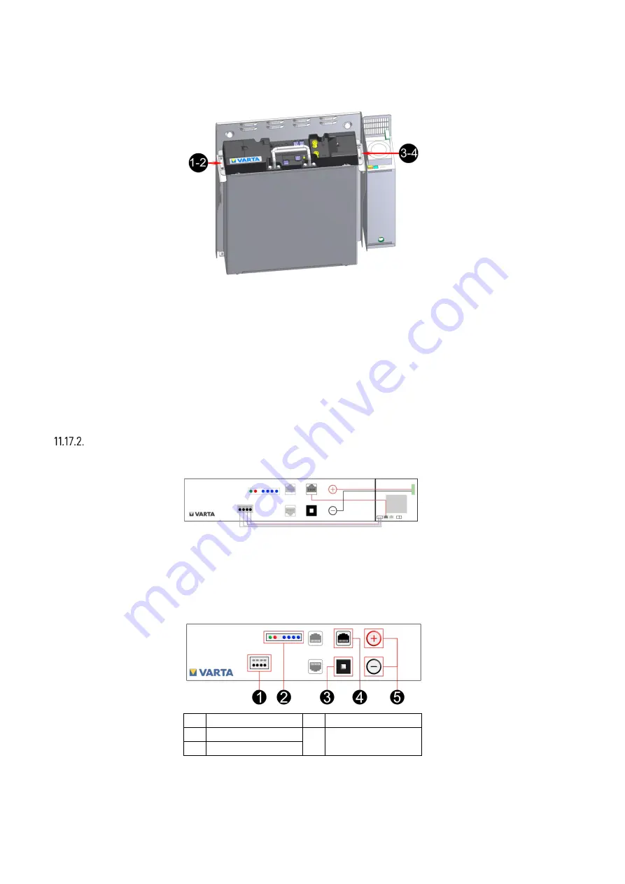
The battery module is positioned as shown in the following figure.
Lift the battery module onto the two tracks of the support plate.
The handle is suitable for moving the battery module only.
The long holes on the battery module serve to centre the battery module with the two pre-fitted
screws.
Push the battery module back
onto
the holding angle.
Fasten the battery module using the four screws delivered.
Connect the battery module
Create the connections on the battery module.
Battery current connection:
Insert the two plugs in the correct polarity.
Each plug must lock audibly in place.
1 DRY contact
4 CAN
2 LED-indicator
5 Battery power
connection
3 Activation button
Summary of Contents for pulse neo
Page 1: ...VARTA STORAGE GMBH OPERATING MANUAL VARTA pulse neo ...
Page 35: ...35 All dimensions in millimetres Fig 2 Dimensions on the support plate ...
Page 77: ...As at 07 2021 Appendix a Connection diagram TN C network ...
Page 78: ...As at 07 2021 Appendix b Connection diagram TT network ...
Page 79: ...As at 07 2021 Appendix c Connection diagram TN C network with data logger ...
Page 80: ...As at 07 2021 Appendix d Connection diagram TT network with data logger ...


