
32 COMMISSIONING AND ADJUSTMENT
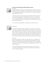
Activating and deactivating optional RH RF switch:
Activation:
Take the ventilation unit plug out of the socket and put it back in again. The
ventilation unit will now search for new switches for 10 minutes. Then take
out the batteries from the sensor and put them back in (see replacement of
batteries of RH RF switch).
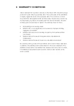
Touch the control zone at the bottom right for at least 3 seconds. When all
of the LEDs are flickering you must release the control zone. If the linking
action is successful the LED in the upper left corner lights up green twice,
and on the right a LED lights up that indicates in which relevant position the
RH RF switch finds itself.
Tip: You can link a single switch to a maximum of 3 ventilation units.
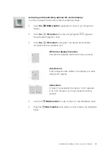
Deactivation:
Kill the switch briefly by taking the batteries out of the sensor and putting
them back in (see replacement of batteries of RH RF switch). The switch can
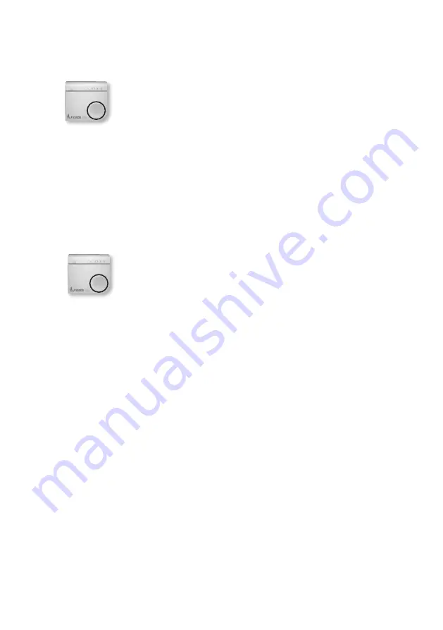
unlink ventilation units for 10 minutes. Touch the control zone at the bottom
right for at least 10 seconds. When all of the LEDs are flickering for the 2nd
time you must release the control zone. In the event of several activated ven-
tilation units, all activated units are deactivated as a result. The LED of the
switch lights up red four times in order to indicate that the units are unlinked.
Attention:
An internal RH sensor is located in the exhaust duct of the ventilation unit.
Both the internal RH sensor and the potential external RH switch indicate
what the recommended air flow should be as a function of the atmospheric
humidity. The ventilation unit will adapt its ventilation flow as a function of the
greatest demand.
The internal RH sensor reacts on the basis of the RH value of the entire
home. The external RH switch reacts only on the basis of the RH value of
the room where it is hanging.


