


32 MISE EN SERVICE ET RÉGLAGE
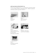
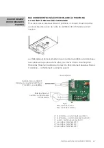
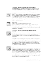
Connexion et déconnexion d’un sélecteur RF HR optionnel
Connexion
Retirez la fiche de l’unité de ventilation de la prise puis enfichez-la à nou-
veau. L’unité de ventilation recherche alors de nouveaux sélecteurs pendant
10 minutes. Retirez les piles du capteur et remettez-les en place (voir rem-
placement des piles du sélecteur RF HR).
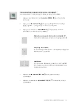
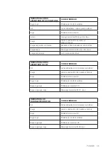
Touchez la zone de commande dans le coin inférieur droit pendant au
moins 3 secondes. Lorsque toutes les LED clignotent, relâchez la zone de
commande. Si la connexion a réussi, la LED dans le coin supérieur gauche
clignote 2x en vert et une LED s’allume à droite pour indiquer la position
dans laquelle se trouve le sélecteur RF HR.
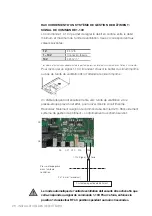
Conseil : vous pouvez connecter un même sélecteur à 3 unités de ventilation
Déconnexion
Mettez brièvement le sélecteur hors tension en retirant les piles du capteur
et en les remettant en place (voir remplacement des piles du sélecteur RF
HR). Le sélecteur peut déconnecter des unités de ventilation durant 10
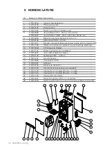
minutes. Touchez la zone de commande dans le coin inférieur droit pendant
au moins 10 secondes. Lorsque toutes les LED clignotent pour la seconde
fois, relâchez la zone de commande. Si plusieurs unités de ventilation sont
connectées, elles seront toutes déconnectées. La LED du sélecteur clignote
4x en rouge pour indiquer que les unités sont déconnectées.
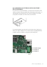
Attention :
La gaine d’évacuation de l’unité de ventilation abrite un capteur HR interne.
Le capteur HR interne et l’éventuel sélecteur RF externe indiquent le débit
d’air recommandé en fonction du taux d’humidité. L’unité de ventilation ajus-
tera son débit de ventilation en fonction de la demande la plus élevée.
Le capteur HR interne réagit en fonction de la valeur HR de l’ensemble du
logement. Le sélecteur HR externe réagit seulement en fonction de la valeur
HR de la pièce où il est installé.


