background image

134

English

E

  150  

C

E

F

B

  127  

  26  

  225  

Q

  184  

  184  

O

O

M

  305  

  225  

N

P

  156  

  156  

C

I

  150  

  26  

  81  

  150  

A

D

E

  150  

C

E

F

B

  127  

  26  

  225  

Q

  184  

  184  

O

O

M

  305  

  225  

N

P

  156  

  156  

C

I

  150  

  26  

  81  

  150  

A

D

1032

1012

C

G

I

O

O

M

  305  

  225  

N

H

H

A

L

I

F

  225  

N

B

  127  

E

E

R

R

D

20

60

98

508

670

670

508

S

84

C

G

I

O

O

M

  305  

  225  

N

H

H

A

L

I

F

  225  

N

B

  127  

E

E

R

R

D

S

84

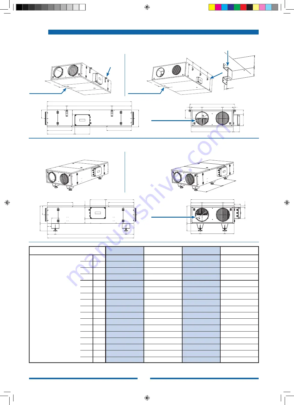
ENY–P4–P

ENY–P4–S

ENY–P1–P / ENY–P2–P / ENY–P3–P

ENY–P1–S / ENY–P2–S / ENY–P3–S

Hole Ø 12 mm

Hole Ø 10 mm

Ø D

(male fitting with

gasket)

Condensate drain

3/4" male

Condensate drain

3/4" male

Ø D

(male fitting with

gasket)

Floor units

Ceiling units

Model

ENY–P1

ENY–P2

ENY–P3

ENY–P4

Dimension

mm

mm

mm

mm

mm

mm

mm

mm

mm

mm

mm

mm

mm

mm

S

R

Q

P

O

N

M

L

I

H

G

F

E

ØD

C

mm

B

mm

A

mm

435
830

670 + 670

508
305

1740

885
359
580

1032 + 1012

1332

20

856

325
600

1328

386
234

1302

758
219
580

1788

882

26

791

295
560

1108

321
190

1202

581
134
500

1438

782

26

678

220
410
908
396
170
902
556

93

500

1388

482

26

654

400

2355
1700

610

2100
1250

470

1750
1150

385

1700

850
344

355

250

250

man_Energy Plus IT-UK-FR-DE-ES-NL-FM_Ultima_Rev_0721.indd   134

man_Energy Plus IT-UK-FR-DE-ES-NL-FM_Ultima_Rev_0721.indd   134

24/01/2022   16:06:22

24/01/2022   16:06:22

Summary of Contents for Energy plus

Page 1: ...rugwinningsunit Pag 2 EN Heat Recovery Unit Pag 126 INSTALLATION USE AND MAINTENANCE INSTRUCTIONS FR R cup rateurs Pag 64 MANUEL D INSTALLATION UTILISATION ET ENTRETIEN Cover Manuale Energy Plus VASCO...

Page 2: ...bladzijde 13 LUCHTSTROMEN OMKEREN bladzijde 13 DE LUCHTSTROMEN VAN PLAFONDUNITS OMKEREN bladzijde 14 DE LUCHTSTROMEN VAN VLOERUNITS OMKEREN bladzijde 15 ENY P1 LUCHTSTROOM bladzijde 16 ENY P2 LUCHTSTR...

Page 3: ...es die uitsluitend door een installateur of een erkende technicus mogen worden uit gevoerd VOOR DE INSTALLATIE Plaats de unit niet in een explosieve corro sieve of vochtige omgeving buiten of in zeer...

Page 4: ...warmtewis selaar niet op de juiste manier tot stand worden gebracht kan er mogelijk warme vloeistof vrijkomen die brandwonden kan veroorzaken Alle panelen en afschermingen die voor onderhoud of repara...

Page 5: ...ische com patibiliteit 2014 30 EU BGS richtlijn 2011 65 EG Richtlijn energiegerelateerde pro ducten ERP 2009 125 EG ALGEMENE INFORMATIE De veiligheidsvoorzieningen niet verwijde ren Als u om een goede...

Page 6: ...onderhoud Verwijdering Alle reparatie of onderhoudswerkzaamhe den moeten worden uitgevoerd door gekwa lificeerde specialisten De fabrikant wijst alle aansprakelijkheid af voor schade die veroorzaakt w...

Page 7: ...rd In deze instructiehandleiding wordt beschre ven hoe de machine moet worden gebruikt op de wijze waarvoor die bedoeld is komen de techni sche eigenschappen van de machine aan bod en wordt er informa...

Page 8: ...uct van stroom te voorzien Nagaan of de invoer uitvoerverbindingen van het product niet versperd zijn Nagaan of alle onderdelen van het pro duct stevig vastzitten aan de bijbehorende afdichtingen De s...

Page 9: ...tie 2 Totaal aantal ventilatoren Nominaal geabsorbeerd vermo gen 3 Maximaal totaal geabsorbeerde stroomsterkte 3 Stroomtoevoer unit 3 Beschermingsklasse met machine ge nstalleerd Gewicht unit ENY P4 E...

Page 10: ...202 581 134 500 1438 782 26 678 325 600 1328 386 234 1302 758 219 580 1788 882 26 791 435 830 670 670 508 305 1740 885 359 580 1032 1012 1332 20 856 mm A mm B mm C D E F G H I L M N O P Q R S mm mm mm...

Page 11: ...Bedieningselementen Warmtewis selaar Ventilator Ventilator Condensaatafvoer Filters Filters VERSE LUCHT AFGEVOERDE LUCHT AANGEVOERDE LUCHT AFGEZOGEN LUCHT Voor de minimale ruimte voor onderhoud en ser...

Page 12: ...t worden vastgemaakt Gebruik de klemmenstrook in het bedieningspaneel voor het maken van de aansluitingen op de netvoeding Het is niet raadzaam om de ENY P4 units aan het plafond te hangen Als dit str...

Page 13: ...at de inlaatventila tor als uitlaatventilator werken en keert de plaat de functies van de sensoren om zodat de luchtaanvoersensor gedetecteerd en beschouwd wordt als de luchtafvoersensor Sensor Id Sta...

Page 14: ...rd de onderstaande aanzichten tonen de machine gekanteld DE LUCHTSTROMEN VAN PLAFONDUNITS OMKEREN In het geval van de plafondunits moet de condensaatopvangbak worden verwijderd om de stromen om te ker...

Page 15: ...e keren Normale vloerinstallatie Omgekeerde stromen van de vloerinstallatie NORMAAL BEDRIJF Positie DIP 1 DIP 1 OFF DIP 1 ON DE LUCHTSTROOM OMKEREN ELEKTRONISCHE PRINTPLAAT ELEKTRONISCHE PRINTPLAAT FI...

Page 16: ...rcuit 1 SFP int 2 UE 1253 14 Debiet Beschikbare statische druk 1 De indicatie van het vermogen dat door de enkele ventilator is geabsorbeerd is nuttig in het geval dat de twee ventilatoren gekalibreer...

Page 17: ...r het enkele circuit 1 SFP int 2 UE 1253 14 Debiet Beschikbare statische druk 1 De indicatie van het vermogen dat door de enkele ventilator is geabsorbeerd is nuttig in het geval dat de twee ventilato...

Page 18: ...et enkele circuit 1 SFP int 2 UE 1253 14 1 De indicatie van het vermogen dat door de enkele ventilator is geabsorbeerd is nuttig in het geval dat de twee ventilatoren gekalibreerd worden bij onevenwic...

Page 19: ...Beschikbare statische druk GEABSORBEERD VERMOGEN door het enkele circuit 1 SFP int 2 UE 1253 14 1 De indicatie van het vermogen dat door de enkele ventilator is geabsorbeerd is nuttig in het geval da...

Page 20: ...2 43 0 70 0 88 1 72 2 52 3 35 4 05 1 06 1 37 2 66 3 90 5 31 6 49 1 50 1 98 3 89 5 87 7 90 9 99 94 3 92 7 90 0 88 4 87 3 86 4 93 5 92 7 90 0 88 4 87 2 86 3 92 9 91 8 89 0 87 4 86 1 85 4 97 5 96 4 93 8...

Page 21: ...n zich voordoen in de avond van een zeer zonnige dag met niettemin een vrij lage buitentemperatuur EAT 21 C Met EAT 20 C is er echter geen vraag naar warmtevoorziening en helpt de frisse lucht de door...

Page 22: ...ngen van de unit moeten door een gekwalificeerde elektricien tot stand worden gebracht De klant is zelf verantwoordelijk voor het aanleggen van de aarding met gebruikmaking van de installatie van het...

Page 23: ...roomvoorziening DEFAULT DIP OFF ON 1 Installatie van F1 inlaat naar links Installatie van F2 inlaat naar rechts 2 Zonder voorverwarming Voorverwarming 3 PWM elektrische weerstand Ventielactuator E w O...

Page 24: ...2 KD1 KD2 F3 Ventilator 2 EC motorregeling uitgangssignalen van printplaat Ingangssignaal snelheidsmeter printplaat voor de modellen ENY P1 ENY P2 en ENY P3 NA uitgangssignaal voor de aansturing op af...

Page 25: ...elektronische printplaat Weerstand voorverwarming ON OFF of actuator warmwa terventiel voor voorverwarming uitgangsspanning 230 Vac Naverwarming uitgangsspanning 230 Vac Nakoeling uitgangsspanning 230...

Page 26: ...eisten aansluitkabel Maximale lengte 20 m Bedrading kan niet gecombineerd worden met 230V hoogspanningska bels Mogelijke combinatie van SELV be drading in AC DC man_Energy Plus IT UK FR DE ES NL FM_Ul...

Page 27: ...m 1 1 c d C 0 1 H C A T ENY P2 ENY P3 T EP vereisten aansluitkabel Maximale lengte 20 m Bedrading kan niet gecombineerd worden met 230V hoogspanningska bels Mogelijke combinatie van SELV bedrading in...

Page 28: ...A m 1 1 c d C 0 1 ENY P4 T EP vereisten aansluitkabel Maximale lengte 20 m Bedrading kan niet gecombineerd worden met 230V hoogspanningska bels Mogelijke combinatie van SELV bedrading in AC DC man_En...

Page 29: ...dmatige reset De voorverwarmingsweerstand moet voor komen dat de warmtewisselaar bevriest en wordt aangestuurd vanaf het bedieningspa neel met modulerende PWM logica om de temperatuur van de afgevoerd...

Page 30: ...onregelmatig kan zijn en de oververhittingsbeveiliging kan inschakelen De verwarmer moet ge soleerd zijn in ove reenstemming met de regelgeving inzake ventilatiebuizen Het isolatiemateriaal moet alti...

Page 31: ...Rood Blauw lichtblauw Oranje Paars Grijs Wit Roze Goud Turquoise Zilver Groen geel Bedrading product Verbinding verantwoorde lijkheid van de installateur Legende man_Energy Plus IT UK FR DE ES NL FM_...

Page 32: ...rdt geregeld door de ON OFF logica om de ingestelde waarde te bereiken van de binnenluchtverwarming die geregeld wordt door de temperatuursensor op de afvoerluchtstroom De weerstand op het toevoercirc...

Page 33: ...al moet altijd brandvertragend zijn Het deksel van de verwarmer moet vrij van isolatiemate riaal zijn zodat het identificatielabel dui delijk zichtbaar is en het deksel verwijderd kan worden Het insta...

Page 34: ...LECTRICHEATER POWERSUPPLY400Vac L1 PE 5 L2 15 17 20 PE 7 19 L3 18 PowerSupply400Vac50Hz N L1 L2 L3 L2 L1 G1 LS3 LS1 G3 L3 22 21 ON 21 Power Board DIP4 ON DIP5 ON 1 EH3 EH4 3 20 5 23 4 KD1 2 22 ON Q2 5...

Page 35: ...um vinnen met 2 5 mm tussen de vinnen koperen verdeelstukken die aan de zijkanten uitsteken De binnenkant van de component bevat de condensaatopvangbak met een afvoeraansluiting van 16 mm De behandeli...

Page 36: ...1 56 16 645 568 676 400 55 180 531 133 300 1 56 16 mm A mm B mm mm mm mm mm mm mm C D E F E1 F1 M P Afmetingen Diameter Condensaatafvoer BAE 4 ENY P4 BAE 3 ENY P3 BAE 1 2 ENY P2 BAE 1 2 ENY P1 9022012...

Page 37: ...handelingsbatterij aanslui ten De batterijcomponent kan gebruikt worden om de lucht te koelen voordat die in de ruimte wordt afgegeven Daarvoor wordt een 2 buizensysteem voor alleen koelen gebru ikt o...

Page 38: ...erwarmer KOELMODUS MET EXTERNE ON OFF 230 Vac VENTIELACTUATOR VERWARMINGSMODUS MET EXTERNE ON OFF EENFASIG 230 Vac ELEKTRISCHE VERWARMER POWER ON 230 Vac SIGNAAL 2 BUIZENMODUS NABEHANDELING BEHANDELIN...

Page 39: ...e juiste manier op het hoogste en laagste punt van het systeem worden geplaatst De lucht moet volledig uit het systeem worden gehaald om een goede werking mogelijk te maken Per slucht door de buizen b...

Page 40: ...s unit worden aangesloten met het ENP hulpstuk Ocean component met voorfilter en elektrostatisch filter Ocean SFE Verbindingsstuk Energy Plus Luchtstroom Ocean SFE component Bedradingsschema De DIP 6...

Page 41: ...volgende speci ficaties voldoen en de afvoerbuis moet een helling van minimaal 3 hebben De sifon is essentieel voor een goede werking van de warmteterugwinningsunit doordat het binnendringen van lucht...

Page 42: ...chadigen Voor normale ventilatietoepassingen is het voldoende om de inlaat en uitlaat te rei nigen met een borstel of water en indien nodig een neutraal schoonmaakmiddel Bij veel vuil mag u perslucht...

Page 43: ...rlies van het filter regelen De verschildrukschakelaar is stan daard ingesteld op 120 Pa Wanneer die waarde wordt bereikt stuurt het bedieningspaneel een onderhoudswaar schuwing naar de wandregelaar e...

Page 44: ...op het typeplaatje van de machine Buissysteem en inlaatpunt reinigen De aansluitingen en behuizing van de unit nakijken en de oorspronkelijke omstandigheden herstellen Naverwarming gebruiken Warmtewis...

Page 45: ...ands 1a 2 3 1b 4 Installatie wandbediening T EP man_Energy Plus IT UK FR DE ES NL FM_Ultima_Rev_0721 indd 45 man_Energy Plus IT UK FR DE ES NL FM_Ultima_Rev_0721 indd 45 24 01 2022 15 11 35 24 01 2022...

Page 46: ...r CO2 3 Wekelijkse programmering Het HOOFDSCHERM biedt de volgen de opties 1 Het voorverwarmingspictogram wijst op activering van de antivriesmodus 2 Een ingesteld waarschuwingspictogram knippert om a...

Page 47: ...rogramma inschakelen Weekprogramma uitschakelen A De machine starten en stopzetten Naar het technische menu alleen bevoegd per soneel wanneer de unit aan staat gedurende 5 seconden tegelijkertijd op d...

Page 48: ...etecteerde werkingsveld op de werking sschema s INBEDRIJFSTELLING b Bevestigen met Enter LET OP wanneer de bevestiging verzonden is wacht het bedieningspaneel even totdat de ventilatorsnelheid de beno...

Page 49: ...irconditioning in de zomer De ontwerpgegevens voor het selecteren van de machine staan hieronder Op basis van het berekende luchtdebiet wordt het Energy Plus model geselecteerd als het meest geschikte...

Page 50: ...110 Pa de ontwerp statische druk van de toevoer en afvoerluchtcircuits van de machine met toevoeging van de drukverliezen door de hulpstukken Ontwerpverschil tussen het toevoer en afvoerluchtdebiet In...

Page 51: ...1 Het apparaat aanzetten met de ON OFF toets 3 3 Het symbool knippert op het display Op Enter drukken om te bevestigen Het TOUCHPAD gebruiken om het symbool P te selecteren en te bevestigen 4 4 Nu het...

Page 52: ...23 24 SNELHEID 45 70 100 Maandag Zondag Weekprogramma P3 DAG UUR 0 1 1 2 2 3 3 4 4 5 5 6 6 7 7 8 8 9 9 10 10 11 12 13 13 14 14 15 15 16 16 17 17 18 18 19 19 20 20 21 21 22 22 24 SNELHEID 45 70 100 DAG...

Page 53: ...kan het reeds be staande programma van een specifieke dag worden geannuleerd om een nieuwe functie in te stellen 5 Als het programmanummer geselecteerd is start de programmeringsprocedure de dag van...

Page 54: ...nfiguration with the mstop OFF parameter the selection of the former speed within the custo mized programme corresponds to the fans stop Als u de instelling van OFF wilt wijzigen zodat die overeenstem...

Page 55: ...met gebruikersinstellingen te gaan Fig 2 De volgende opties zijn beschikbaar HANDBEDIENDE VENTILATIEMODUS AUTO AUTOMATISCHE MODUS WEKELIJKSE PROGRAMMERINGSMODUS DAG en TIJD INSTELLEN Fig 1 Fig 2 Op M...

Page 56: ...snelheid van de ventilator verhoogd in tegenwijzerzin bewe gen verlaagt de snelheid van de ventilator De modus Automatisch kan alleen worden ingeschakeld wanneer de units met geavan ceerde centrale r...

Page 57: ...De dag van de week als volgt instellen dag 1 maandag dag 2 dinsdag dag 3 woensdag dag 7 zondag Druk op de toets M overloop met de TOUCH PAD tot de functie P begint te knippe ren en bevestig met de toe...

Page 58: ...ncomfort en buitentempe raturen tot 10 C te handhaven en om de degeneratieve vorming van ijs te voorkomen bij uitblazing tot 15 C buiten De elektrische weerstand wordt gemonteerd met een veiligheidsth...

Page 59: ...val wordt het proces vrije verwarming genoemd Energy Plus units zijn uitgerust met een bypassklep die de warmtewisselaar omzeilt om vrije koeling mogelijk te maken of vrije verwarming De klep wordt aa...

Page 60: ...zen uit dag en tijd instellen instellen eerste configuratie van de ventila toren V selecteren Instellen van het gekozen weekpro gramma P FCtry menu FACTORY Op Enter drukken om te bevestigen 2 Tegelijk...

Page 61: ...rs van het apparaat wijzigen Met de regelaar ON tegelijkertijd 3 seconden op M en ON OFF drukken Het menu PAr selecteren met het TOUCHPAD en bevestigen met Enter De te wijzigen parameter selecteren me...

Page 62: ...electie om het menu te verlaten drie keer op M drukken BESCHRIJVING T1 waarde van buitenluchttemperatuur sen sor T1 T2 waarde van inlaatluchttemperatuur sensor T2 T3 waarde van temperatuur afgezogen l...

Page 63: ...nigen of vervangen Als het filter gereinigd is verdwijnt het pictogram automatisch 1 Storing IAQ filter 3 Storing elektrische ontdooi ingsweerstand De resetthermostaat van de weerstand controleren De...

Page 64: ...VERSION DES FLUX D AIR 13 INVERSION DES FLUX D AIR UNIT AU PLAFOND 14 INVERSION DES FLUX D AIR UNIT AU SOL 15 PERFORMANCES A RAULIQUES ENY P1 16 PERFORMANCES A RAULIQUES ENY P2 17 PERFORMANCES A RAULI...

Page 65: ...lis es exclusivement par un installateur ou un technicien agr POUR L INSTALLATION Ne pas installer dans une atmosph re explo sive ou corrosive dans des endroits humi des l ext rieur ou dans des pi ces...

Page 66: ...hydroniques ne sont pas manipul scorrectement le fluide caloporteur chaud peut s en chapper et causer des br lures Tous les panneaux et capots enlev s pour les interventions d entretienou de r para ti...

Page 67: ...Directive RoHS 2011 65 EC Directive Energy Related Products ERP 2009 125 EC RECOMMANDATIONS G N RALES Il est imp ratif de ne pas retirer les dispo sitifs de s curit Toutefois s il est n ces saire de r...

Page 68: ...il doivent tre effectu s par du person nel sp cialis et qualifi Le constructeur d cline toute responsabilit en cas de dom mages dus des modifications ou d t rio rations de l appareil CONSIGNES POUR L...

Page 69: ...allateur et il doit toujours tre port e de main pour consultation en cas de besoin Le manuel d instructions doit tre toujours disponible pour la consultation et conserv dans un endroit sec et prot g L...

Page 70: ...rifier que les raccordements d entr e sortie ne sont pas bouch s Contr ler que tous les composants sont solidement fix s leurs garnitures Tourner manuellement les h lices de chaque ventilateur pour v...

Page 71: ...cup r e 2 Nombre total de ventilateurs Puissance lectrique absorb e nominale 3 Courant absorb maximal total 3 Alimentation unit 3 Indice de protection machine install e Poids unit ENY P4 ENY P3 ENY P...

Page 72: ...1202 581 134 500 1438 782 26 678 325 600 1328 386 234 1302 758 219 580 1788 882 26 791 435 830 670 670 508 305 1740 885 359 580 1032 1012 1332 20 856 mm A mm B mm C D E F G H I L M N O P Q R S mm mm...

Page 73: ...andes changeur Ventilateur Ventilateur Vidange Filtres Filtres AIR EXT RIEUR AIR VICIE EXPULS AIR D INSUFFLATION AIR AMBIANT EXTRAITE Voir chapitre Entretien pour le d gagement minimum requis pour l e...

Page 74: ...tre ind pendante de celle de l unit Pour les raccordements l alimentation lectrique utiliser le bornier plac sur le panneau de commande de l unit Il est d conseill d installer au plafond les unit s EN...

Page 75: ...e puissance De cette fa on le ventilateur d insufflation devient celui d extraction et la carte inverse la fon ction des sondes la sonde de reprise d air sera d finie et consid r e comme la sonde d ai...

Page 76: ...t la machine l en vers INVERSION DES FLUX D AIR UNIT AU PLAFOND En cas d unit au plafond pour pouvoir inverser les flux il est n cessaire de d pla cer le bac condensats Configuration standard au plafo...

Page 77: ...es flux d air Configuration standard au sol Configuration flux invers s au sol EX CUTION STANDARD Position DIP 1 DIP 1 OFF DIP 1 ON EX CUTION FLUX INVERSE CARTE LECTRONIQUE CARTE LECTRONIQUE FILTRE M6...

Page 78: ...ISSANCE LECTRIQUE AB SORB E par chaque circuit 1 SFP int 2 UE 1253 14 D bit Pression statique disponible 1 L indication de la puissance absorb e par chaque ventilateur est utile si les d bits des vent...

Page 79: ...DE REPRISE PUISSANCE LECTRIQUE AB SORB E par chaque circuit 1 SFP int 2 UE 1253 14 D bit Pression statique disponible 1 L indication de la puissance absorb e par chaque ventilateur est utile si les d...

Page 80: ...TILATION DE SOUFFLAGE ET DE REPRISE D bit Pression statique disponible PUISSANCE LECTRIQUE AB SORB E par chaque circuit 1 SFP int 2 UE 1253 14 1 L indication de la puissance absorb e par chaque ventil...

Page 81: ...TILATION DE SOUFFLAGE ET DE REPRISE D bit Pression statique disponible PUISSANCE LECTRIQUE AB SORB E par chaque circuit 1 SFP int 2 UE 1253 14 1 L indication de la puissance absorb e par chaque ventil...

Page 82: ...2 52 3 35 4 05 1 06 1 37 2 66 3 90 5 31 6 49 1 50 1 98 3 89 5 87 7 90 9 99 94 3 92 7 90 0 88 4 87 3 86 4 93 5 92 7 90 0 88 4 87 2 86 3 92 9 91 8 89 0 87 4 86 1 85 4 97 5 96 4 93 8 92 1 90 9 90 0 0 79...

Page 83: ...cas par exemple le soir apr s une jour n e o les apports solaires ont t lev s mais o toutefois la temp rature de l air ext rieur est assez fra che TAE 21 C Cependant TAE tant 20 C il n y aura pas de d...

Page 84: ...ts lectriques doivent tre r a lis s par un lectricien qualifi Le client devra raccorder l appareil au r seau de terre du b timent et r aliser un circuit d alimenta tion d di isol et muni d une protect...

Page 85: ...OFF ON 1 Installation GCHE F1 insufflation Installation DTE F2 insufflation 2 Absence pr chauffage Pr sence pr chauffage 3 R sistance lectrique PWM Actionneur vanne R sistance lectrique ON OFF 4 Post...

Page 86: ...RH CO2 RS485 CONTROL DL2 KD1 KD2 F3 Ventilateur 2 Signaux de contr le moteur EC en sortie carte Signal tachym trique en entr e carte pour mod les ENY 1 ENY P2 et ENY P3 Signal de sortie NA pour d port...

Page 87: ...Carte lectronique de contr le Fusible carte lectronique Sortie 230 Vac r sistance pr chauffage ON OFF ou actionneur vanne chaude de pr chauffage Sortie 230 Vac post chauffage Sortie 230 Vac post refro...

Page 88: ...ent T EP Longueur max 20m Il est interdit de poser ensemble le c ble de raccordement et des c bles en 230 V Le passage commun avec des c bles en courant continu ou altern SELV est permis man_Energy Pl...

Page 89: ...P2 ENY P3 Caract ristiques c ble de raccor dement T EP Longueur max 20m Il est interdit de poser ensemble le c ble de raccordement et des c bles en 230 V Le passage commun avec des c bles en courant c...

Page 90: ...ristiques c ble de raccorde ment T EP Longueur max 20m Il est interdit de poser ensemble le c ble de raccordement et des c bles en ten sion 230 V Le passage commun avec des c bles en courant continu...

Page 91: ...La r sistance de pr chauffage assure la mise hors gel de l changeur de chaleur et elle est pilot e par la carte de contr le avec une logique modulante PWM afin que la temp ra ture de l air expuls rest...

Page 92: ...et que la protection thermique de surchauffe ne se d clenche La batterie de chauffe doit tre isol e comme pr vu par la r glementation en vigueur relative aux conduits de ventila tion Le mat riau isola...

Page 93: ...Marron Vert Rouge Bleu Orange Violet Gris Blanc Rose Or Turquoise Argent Vert jaune C blage d usine C blage effectuer par l installateur L gende man_Energy Plus IT UK FR DE ES NL FM_Ultima_Rev_0721 i...

Page 94: ...r le contr le avec une logique ON OFF afin d obtenir la consigne de chauffage de l air ambiant con tr l e l aide de la sonde de temp rature plac e sur le flux de reprise Un thermostat est install sur...

Page 95: ...ts de ventilation Le mat riau isolant doit tre ignifuge Le capot de la bat terie de chauffe ne doit pas tre isol e afin que la plaque d identification avec le nom soit visible et qu il soit possible d...

Page 96: ...CTRICHEATER POWERSUPPLY400Vac L1 PE 5 L2 15 17 20 PE 7 19 L3 18 PowerSupply400Vac50Hz N L1 L2 L3 L2 L1 G1 LS3 LS1 G3 L3 22 21 ON 21 Power Board DIP4 ON DIP5 ON 1 EH3 EH4 3 20 5 23 4 KD1 2 22 ON Q2 5 3...

Page 97: ...rieur de la sec tion est plac le bac condensats avec raccord d vacuation de 16 mm La section de traitement est adapt e aussi bien pour le post chauffage que pour le refroidissement de l air d insuffl...

Page 98: ...568 676 400 55 180 531 133 300 1 56 16 mm A mm B mm mm mm mm mm mm mm C D E F E1 F1 M P Dimensions Diam tre vacuation condensats BAE 4 ENY P4 BAE 3 ENY P3 BAE 1 2 ENY P2 BAE 1 2 ENY P1 9022012 690 540...

Page 99: ...t La section batterie peut tre utilis e pour refroidir l air avant de l insuffler dans la pi ce installation 2 tubes en rafraichisse ment seul ou pour refroidir chauffer instal lation 2 tubes r versib...

Page 100: ...stance lec trique MODE REFROIDISSEMENT AVEC ACTIONNEUR VANNE ON OFF 230 VAC EXT RIEUR MODE CHAUFFAGE AVEC BATTERIE DE CHAUFFE LECTRIQUE EXT RIEUR ON OFF MO NOPHAS E 230 Vac SIGNAL POWER ON 230 Vac POS...

Page 101: ...les plus hauts et les plus bas de l installation L air ventuellement pr sent dans l installation doit tre purg pour assurer un bon fon ctionnement Pour v rifier que la batterie de chauffe est compl t...

Page 102: ...Energy Plus gr ce l accessoire rac cordPl num ENP Section avec pr filtre et filtre lectrost Crystall Ocean SFE Plenum Energy Plus Flux d air Section SFE Ocean Raccordement lectrique Le DIP 6 doit tre...

Page 103: ...t le fon ctionnement normal Le siphon doit respecter les exigences sui vantes et la tuyauterie d vacuation doit avoir une pente minimale de 3 Indispensable au bon fonctionnement du r cup rateur de cha...

Page 104: ...tr e et la sortie avec une brosse ou avec de l eau et si n cessaire un d tergent neutre En cas de salet impor tante il est possible d utiliser de l air com prim ou de laver avec de l eau sous haute pr...

Page 105: ...diff rentiels qui contr lent la perte de charge du filtre Le r glage d usine du pressostat diff rentiel est 120 Pa Lorsque cette valeur est atteinte la carte de contr le envoie une alerte de demande d...

Page 106: ...conforme la valeur indiqu e surs la plaque signal tique du moteur Nettoyer le r seau de gaines et la bouche d aspiration Contr ler les raccordement et l enveloppe de l unit et r tablir les conditions...

Page 107: ...a 2 3 1b 4 Installation de la commande murale T EP man_Energy Plus IT UK FR DE ES NL FM_Ultima_Rev_0721 indd 107 man_Energy Plus IT UK FR DE ES NL FM_Ultima_Rev_0721 indd 107 24 01 2022 16 22 35 24 01...

Page 108: ...s suivantes 1 En cas de Mode hors gel l ic ne du pr chauffage s allume 2 Une ic ne de signalisation clignote pour sugg rer le remplacement des filtres 3 Une ic ne de signalisation registre de by pass...

Page 109: ...fonctionnement D sactivation programme de fonctionnement A Mise en marche et arr t de la machine Entrer dans le Menu Technicien uniquement personnel autoris quand l unit est sur ON on acc de au menu...

Page 110: ...s les dia grammes de fonctionnement b Valider avec la touche Enter MISE EN MARCHE ATTENTION quand on valide la commande attend quelques instants que le nombre de tours du ventilateur atteigne le r gi...

Page 111: ...maire comme vecteur nerg tique pour contribuer la climatisation estivale Les donn es de calcul permettant de s lectionner la machine sont r sum es ci dessous On choisit le mod le Energy Plus le mieux...

Page 112: ...230 Pa 110 Pa la pression statique disponible nominale des circuits air d insufflation et de reprise l ext rieur de la machine laquelle plus les pertes dues aux accessoires Le d s quilibre pr vu entre...

Page 113: ...P1 P2 P3 P4 1 Allumer l appareil l aide de la touche ON OFF 3 Sur l cran le symbole clignote Appuyer sur la touche Enterpour valider Se positionner sur le symbole P l aide du TOUCH PAD et valider 4 C...

Page 114: ...22 23 23 24 VITESSE 45 70 100 Lundi Dimanche Programme hebdomadaire P3 JOUR HEURE 0 1 1 2 2 3 3 4 4 5 5 6 6 7 7 8 8 9 9 10 10 11 12 13 13 14 14 15 15 16 16 17 17 18 18 19 19 20 20 21 21 22 22 24 VITES...

Page 115: ...mer le programme pr existant pour une journ e donn e avant d en d finir un nouveau 5 Une fois le num ro du programme s lec tionn la proc dure de programmation commence saisir le jour de la semaine sai...

Page 116: ...ard avec le param tre mstop OFF la s lection de la premi re vitesse dans la pro grammation personnalis e repr sente l arr t des ventilateurs Pour modifier la programmation de off de fa on ce qu il cor...

Page 117: ...grammations Utili sateur appuyer sur la touche M Fig 2 Les options disponibles sont MODE VENTILATION MANUELLE AUTO MODE AUTOMATIQUE MODE PROGRAMME HEBDOMADAIRE PROGRAMMATION HEURE et JOUR Fig 1 Fig 2...

Page 118: ...se du ventila teur dans le sens inverse des aiguilles d une montre on diminue la vitesse du ventilateur La Fonction automatique peut tre activ e uniquement si les unit s sont quip es de syst mes de co...

Page 119: ...ou diminuer la valeur Utiliser la touche Valider pour con firmer et passer la programmation suivante Pour la programmation du jour de la semaine tenir compte que jour 1 lund jour 2 mard jour 3 mercred...

Page 120: ...eur jusqu des temp ratures ext rieures de 10 C et dans le but d viter la formation de glace sur l expulsion jusqu 15 C La r sistance lectrique est munie d un ther mostat de s curit qui d sactive l uni...

Page 121: ...i ser directement l air ext rieur pour chauffer la pi ce occup e dans ce cas on parle de free heating Les unit s Energy Plus sont munies d un registre de by pass qui permet d exclure l changeur de r c...

Page 122: ...mmation jour et heure programmation configuration initiale des ventilateurs V Choix Programmation du programme hebdo madaire choisi P menu FCtry FACTORY Appuyer sur la touche enter pur valider 2 Appuy...

Page 123: ...activ 10 30 C 26 C Ce menu permet de modifier les param tres de fonctionnement de l appareil Avec la commande sur ON appuyer en m me temps sur les touches M et On Off pendant 3 secondes Choisir le me...

Page 124: ...u choix des param tres pour quitter le menu appuyer 3 fois sur la touche M DESCRIPTION T1 valeur sonde temp rature air ext rieur T1 T2 valeur sonde temp rature air de soufflage T22 T3 valeur sonde tem...

Page 125: ...iltres ma chine lorsque les filtres sont propres l ic ne disparait automatiquement 1 Panne filtre IAQ 3 Panne r sistance lectrique de d givrage V rifier thermostat r armement r si stance V rifier racc...

Page 126: ...THE AIR FLOWS 13 INVERTING THE AIR FLOWS OF CEILING UNITS 14 INVERTING THE AIR FLOWS OF FLOOR UNITS 15 ENY P1 AIRFLOW PERFORMANCE 16 ENY P2 AIRFLOW PERFORMANCE 17 ENY P3 AIRFLOW PERFORMANCE 18 ENY P4...

Page 127: ...clusively by an installer or authorized technician Operations which may be carried out by the user Warning Particularly important and or deli cate operations Carefully read the following user informat...

Page 128: ...at the fan has stopped Flow and return valves and any isolating valves must be closed for repair and maintenance Never tamper with or modify regulation and safety devices without prior authorisation a...

Page 129: ...ent we always aim to provide state of the art products compliant with current safety standards The rules and guidelines in this document therefore reflect compliance with the safety regulations and pr...

Page 130: ...osal All repairs or maintenance must be perfor med by qualified specialists The manufacturer declines all responsibility for damage caused by modifications or tam pering with the unit IDENTIFICATION L...

Page 131: ...e for consultation and be preserved in a protected and dry place The instruction manual aims to describe how to use the machine the way the machine is designed to be used the machine s technical featu...

Page 132: ...n of the fans Disassembly and reassembly must be car ried out by qualified staff as they do not fall under routine maintenance RECEIPT OF THE UNIT HANDLING AND START RECEIPT OF THE UNIT Each product i...

Page 133: ...5 4 90 9 1 80 600 250 0 47 1700 230 1 N 50Hz 154 IP20 3 4 770 2 10 5 90 6 2 80 300 220 0 32 1150 230 1 N 50Hz 110 IP20 2 8 330 2 6 5 90 3 9 80 270 170 0 20 720 230 1 N 50Hz 290 IP20 6 5 1460 2 24 5 94...

Page 134: ...3 4 male Condensate drain 3 4 male D male fitting with gasket Floor units Ceiling units Model ENY P1 ENY P2 ENY P3 ENY P4 Dimension mm mm mm mm mm mm mm mm mm mm mm mm mm mm S R Q P O N M L I H G F E...

Page 135: ...STED AIR UNIT DRAWING Filter Filter change see Maintenance chapter 1 Damper 2 Filters 3 Control board 4 Siphon connection 5 Air fan 6 Air fan 7 Heat recovery unit 8 Collection tray MAINTENANCE SIDE VI...

Page 136: ...ng the connections to the ducted system or condensate discharge pipe discharge side and the electrical connec tions The ducted system must be secured indepen dently from the unit Use the terminal bloc...

Page 137: ...tion Turning the bolt in the mounting feet rai ses or lowers the corner of the unit In this way the unit can be adjusted to be made horizontal AIR DUCT CONNECTIONS Sensor Id Standard Air Flow Rate Inv...

Page 138: ...thecondensatetray needstobemovedinordertoinverttheflows This operation is simple and involves the remo val of the three lower panels and disassem bly of the condensate tray for reassembly on the oppos...

Page 139: ...N Inverted Flows of Floor Installation Typical Floor Installation INVERTING THE AIR FLOWS OF FLOOR UNITS The floor units are equipped with two sepa rate condensate trays for the option of inversion of...

Page 140: ...ly in the event of flow rates balanced between supply and return Flow rate Available static pressure SFP int 2 UE 1253 14 ELECTRICAL POWER ABSORBED by the single circuit 1 SUPPLY AND RETURN VENTILATIO...

Page 141: ...the SFPint apply in the event of flow rates balanced between supply and return Flow rate Available static pressure SFP int 2 UE 1253 14 ELECTRICAL POWER ABSORBED by the single circuit 1 SUPPLY AND RE...

Page 142: ...y in the event of flow rates balanced between supply and return SFP int 2 UE 1253 14 ELECTRICAL POWER ABSORBED by the single circuit 1 Flow rate Available static pressure SUPPLY AND RETURN VENTILATION...

Page 143: ...verify the SFPint apply in the event of flow rates balanced between supply and return SFP int 2 UE 1253 14 ELECTRICAL POWER ABSORBED by the single circuit 1 Flow rate Available static pressure SUPPLY...

Page 144: ...1 37 2 66 3 90 5 31 6 49 1 50 1 98 3 89 5 87 7 90 9 99 0 62 0 90 1 74 2 55 3 35 4 13 1 22 1 50 2 90 4 25 5 57 6 88 1 81 2 38 4 57 6 71 9 06 10 87 2 58 3 49 6 72 10 14 13 50 16 81 91 7 89 8 86 4 84 5 8...

Page 145: ...electrical pre heating resistance In the event of installation in cold climates indicatively with air temperatures below 5 C to prevent the formation of ice inside the heat exchanger you must install...

Page 146: ...onnect the electrical power supply before carrying out any work on the unit All electrical connections of the unit should be made by a qualified electrician It is the customer s responsibility to set...

Page 147: ...1 intake to left 1 ON OFF DIP DEFAULT Configuration DIP switches The electronic board is equipped with a set of 10 Dip switches for configuring the unit i e the direction of use of the fans and any ac...

Page 148: ...tput signals from board Board tachometer input signal for ENY P1 ENY P2 and ENY P3 models FC FC NA output signal for the remote control of alarms or to enable Crystall filter acti vation depending on...

Page 149: ...put Post heating 230 Vac output Resistance preheating ON OFF or hot valve actuator for preheating 230 Vac output Fuse of the electronic power board Electronic control board Purple Gold Orange 5x20F 8...

Page 150: ...cable requirements Max lenght 20 m Not possible combination of wiring with 230V high voltage cables Possible combination of SELV wiring in AC DC ENY P1 man_Energy Plus IT UK FR DE ES NL FM_Ultima_Rev_...

Page 151: ...1 1 c d C 0 1 H C A T T EP connecting cable requirements Max lenght 20 m Not possible combination of wiring with 230V high voltage cables Possible combination of SELV wiring in AC DC ENY P2 ENY P3 ma...

Page 152: ...A m 1 1 c d C 0 1 T EP connecting cable requirements Max lenght 20 m Not possible combination of wiring with 230V high voltage cables Possible combination of SELV wiring in AC DC ENY P4 man_Energy Plu...

Page 153: ...z 3Ph Pe 3 0 230V 50Hz 1Ph Pe 2 1 Code ELECTRICANTIFREEZECOIL BEP to be placed on the External air intake duct Electric heating coil consisting of armored elements inserted inside a galvanised she et...

Page 154: ...e insula tion material must always be flame retardant The cover of the heater must be free of insu lation so that the identification tag can be clearly seen and the cover can be removed The installati...

Page 155: ...n Red Blue light blue Orange Purple Grey White Pink Gold Turquoise Silver Green yellow Production wiring Connection responsibility of the installer Legenda man_Energy Plus IT UK FR DE ES NL FM_Ultima_...

Page 156: ...Air flow rate m3 h ELECTRIC POST HEATING COIL BER to be placed on the Intake air duct Electric heating coil consisting of armored elements inserted inside a galvanised sheet metal duct section with ci...

Page 157: ...heater must flow in the direc tion indicated by the arrow on the side of the heater near the terminal block The heater can be installed in a vertical or horizontal duct and must be made of fire retar...

Page 158: ...ECTRICHEATER POWERSUPPLY400Vac L1 PE 5 L2 15 17 20 PE 7 19 L3 18 PowerSupply400Vac50Hz N L1 L2 L3 L2 L1 G1 LS3 LS1 G3 L3 22 21 ON 21 Power Board DIP4 ON DIP5 ON 1 EH3 EH4 3 20 5 23 4 KD1 2 22 ON Q2 5...

Page 159: ...drain fitting The treatment section is suitable both for post heating and for cooling the intake air The sections of post treatment valves can be managed by the main board The valves are open when th...

Page 160: ...s P M G F1 E1 F E D C mm mm mm mm mm mm mm B mm A mm 645 568 676 400 55 180 531 133 300 1 56 16 645 568 676 355 55 180 531 133 300 1 56 16 536 468 567 250 55 180 431 133 250 1 56 16 9022014 9022013 90...

Page 161: ...er cooling temperature on return air is not reached and closed if it is Air flow Energy Plus Connecting Duct Ocean air handling section with 4 row coil Ocean The coil section is equipped with a 4 row...

Page 162: ...ACTUATOR HEATING MODE WITH EXTERNAL ON OFF SINGLE PHASE 230Vac ELECTRIC HEATER POWER ON 230Vac SIGNAL POST TREATMENT 4 PIPES MODE COOLING MODE WITH EXTERNAL ON OFF 230Vac VALVE ACTUATOR HEATING MODE W...

Page 163: ...ld up of dust After cleaning remove all dust deposits before starting the fan MAINTENANCE OF THE WATER COIL HYDRAULIC CONNECTIONS FOR WATER COIL The connections for the pipes of the heater should not...

Page 164: ...ection is equipped with a Crystall elec trostatic filter suitable for purifying air Installation notes The Ocean SFE section can be connected to the Energy Plus unit using the ENP plenum accessory man...

Page 165: ...proper drainage of the condensate The system must be pressurised as follows H1 2P H2 H1 2 Where P max operating pressure of the heat recovery unit in mm approx 1 mm approx 9 81 Pa CO2 SENSOR accessor...

Page 166: ...n ger and panel back in place Make sure to tighten all the bolts at a torque of 25 Nm MAINTENANCE CLEANING THE EXCHANGER AND ACCESS TO THE FILTERS FROM THE SIDE To remove the heat exchanger for cleani...

Page 167: ...the pressure drop of the filter Install the new filter and then close the panel and secure it with the Philips screws REPLACING THE FILTERS SIDE ACCESS Undo the Phillips head screws in the panels of t...

Page 168: ...ngine s rating plate Clogged heat exchanger Dirty filter Insufficient rotation speed Underestimated pressure drops Formation of frost on the exchanger Damaged impeller Missing or improperly fitted sip...

Page 169: ...sh 1a 2 3 1b 4 T EP Wall control installation man_Energy Plus IT UK FR DE ES NL FM_Ultima_Rev_0721 indd 169 man_Energy Plus IT UK FR DE ES NL FM_Ultima_Rev_0721 indd 169 24 01 2022 16 07 27 24 01 2022...

Page 170: ...igured by the installer 2 Automatic Mode available for units equipped with air quality sensor CO2 3 Weekly Programming T EP TOUCH CONTROLLER Introduction This device was designed for the control of co...

Page 171: ...ation speed or the parameters Scroll between functions 1 Manual Ventilation function 3 AUTO Automatic mode 4 Time setting Current day setting 5 P Weekly program activation Weekly program deactivation...

Page 172: ...ON OFF key on the display b Confirm using the Enter ATTENTION once the confirmation is sent the controller waits just a few moments that the fan speed reaches the necessary value before the V2 calibra...

Page 173: ...formance in an average sized store The ventilation unit is to be inserted in a 4 pipe central air conditioning system provided by the owner and used for water terminals The store is located in a clim...

Page 174: ...in relation to the actual flow rate measurements carried out during commissioning of the system Design imbalance between the supply and return air flow rate In this case the supply return ratio is 80...

Page 175: ...d 4 free programs that can be modified at will Selection of the preset weekly pro gram Programs P1 P2 P3 P4 Setting of the weekly program 3 The symbol flashes on the display Press Enter to confirm Use...

Page 176: ...0 10 11 12 13 13 14 14 15 15 16 16 17 17 18 18 19 19 20 20 21 21 22 22 24 SPEED 45 70 100 DAY TIME 0 1 1 2 2 3 3 4 4 5 5 6 6 7 7 8 8 9 9 10 10 11 11 12 12 13 13 14 14 15 15 16 16 17 17 18 18 19 19 20...

Page 177: ...re is a Reset function that al lows to cancel the pre existing program on a specific day before to set up a new function 5 Once the program number is selected the programming procedure begins enter th...

Page 178: ...d within the custo mized programme corresponds to the fans stop In case you want to modify the OFF setting so that corresponds to the holding minimum flow rate see PAr parameters menu and modify the m...

Page 179: ...GY PLUS OPERATIONAL PROCEDURES Press M to access the User Settings Menu Fig 2 The following options are available MANUAL VENTILATION MODE AUTO AUTOMATIC MODE WEEKLY PROGRAM MODE CURRENT DAY and TIME S...

Page 180: ...r quality With the Manual ventilation mode enabled the speed of the fan at the various points can be adjusted by turning a finger round on the TOUCH PAD Turning a finger clockwise on the pad increases...

Page 181: ...the wheel to set the hour Press Confirm and scroll again to set the minutes Press Confirm and scroll again to set the current day If this icon is present it means that a scheduled program is active T...

Page 182: ...circuit opposite In fact when the external air drops below the critical temperature posing the risk of freezing of the discharged air the resistance is activated and modulates the heat output to keep...

Page 183: ...n as free heating Energy Plus units are equipped with a bypass damper that disables use of the recovery exchanger to permit free cooling or free hea ting The damper is controlled on the basis of a log...

Page 184: ...rer Password protected menu Pressthe M buttononcetoreturntoparameter selection to exit the menu press the M button 3 times 2 Press the ON OFF and M Menu keys at the same time TECHNICAL MENU 1 Turn on...

Page 185: ...er selection to exit the menu press the M button 3 times FUNCTION DESCRIPTION RANGE DEFAULT VLO Minimum control voltage 10 0 see table 2 VHI Maximum control voltage 0 10 see table 2 nLO Minimum speed...

Page 186: ...ration of power board dip switch Thismenuallowsyoutoreadsometheoperating parameters of the appliance With the controller ON press M and ON OFF simultaneously for 3 seconds Select the rEAd menu using t...

Page 187: ...the ma chine At cleaned filter the icon automatically disappears 1 IAQ filter fault 3 Electric defrost resistance fault Check the resistance reset thermostat Check the electrical connections It is re...

Page 188: ...014 o EN 60335 2 80 2003 A1 2004 A2 2009 Richtlijn 2011 65 EU RoHs o EN 50581 2012 Richtlijn 2014 30 EU EMC Richtlijn o EN 55014 1 2006 A1 2009 A2 2011 o EN 55014 2 2015 o EN 61000 3 2 2014 o EN 61000...

Page 189: ...A11 2014 o EN 60335 2 80 2003 A1 2004 A2 2009 Directive 2011 65 EU RoHs o EN 50581 2012 Directive 2014 30 EU directive CEM o EN 55014 1 2006 A1 2009 A2 2011 o EN 55014 2 2015 o EN 61000 3 2 2014 o EN...

Page 190: ...90 01 07 00 Kruishoefstraat 50 B 3650 Dilsen T 32 0 89 79 04 11 F 32 0 89 79 05 00 info vasco eu www vasco eu...

Reviews: