background image

Assembly 

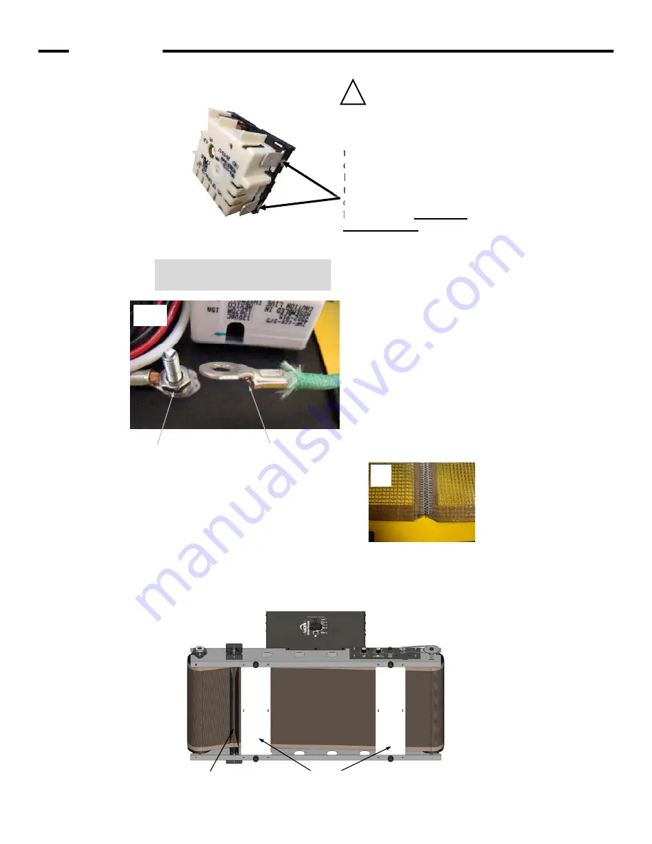
Heater Wire Connections 

Heater Wires (tan wires) have 
push on connectors. Attach 
either wire onto either open 
terminal (indicated on the left) 
on the heat control. 
It does not matter which wire 
to which terminal. Align the 
connector with the tab on the 
heat control and 

push firmly 

until fully seated

. It should be 

hard to push them on, we want 
a tight connection. Pull gently 
on each connector, it should be 
held firmly onto the tab.  

Push any extra slack in the wires, back 
up thru the hole in the conveyor bed. 

See photo 

10B

 for 

Ground Wire Connection  

10B. Ground Wire Connection 

Remove the wingnut and lock washer. 
Place the green ground wire with the ring    
terminal oriented as shown, onto the 
grounding stud. Secure with lock washer 
and wingnut. 

Tighten nut securely. 

Grounding Stud 

Ring Terminal 

10A


10B


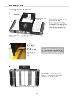
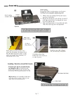
Belt Installation


1)  While dryer is on its side, pass the belt over the aligner 

bar and both braces. 

2)  Carefully lay the dryer back onto its feet. 
3)  Align the edges of the belt and insert the belt connecting 

pin. See enlarged view below. 

4)  Center belt on both rollers. Raise both sides of the belt 

aligner equally approximately 1-1/2”. 

Do Not 

over tension belt, tension only enough to eliminate 

any belt slip on drive pulley. 

Belt Installation and Tracking 

Braces 

Aligner Bar 

11


Align the edges of the belt. 
Insert the belt connecting pin. 
Pin ends can be trimmed if desired 

11


Pg. 10

Summary of Contents for D-100

Page 1: ...Nieuwstad 100 1381 CE Weesp The Netherlands Tel 31 0 294 48 33 55 Fax 31 0 294 41 46 87 Serial Number Please log your machine s serial number and date of purchase for future reference Date ____ ____...

Page 2: ...he area Children and pets must be kept clear of the work area Do not place any objects on top of the drying chamber Surfaces are hot Never leave equipment unattended Do not operate conveyor or dryer w...

Page 3: ...es or until the heater has cooled to 300 F 149 C or lower If the belt is stopped while the heater is hot belt damage will occur Switch machine OFF and disconnect from power before beginning any adjust...

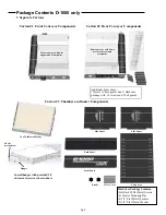
Page 4: ...ront Panel Wire Cover Knobs Carton 3 Chamber Components Carton 2 16 x 16 Infrared Heater Hardware Package Contains 36 Black 8 Sheet Metal Screws 4 Heater Mounting Pins 4 3 8 Flat Metal Washers 2 3 8 F...

Page 5: ...controls and rear pulley Additional items above 1 Belt 1 Chain guard and 1 Hardware package with 18 screws and 2 belt guards Front conveyor with belt aligner and front pulley 16 x 20 Infrared Heater...

Page 6: ...eep it centered The belt does not have to be perfectly centered on the pulley but should not be hanging over either edge Pulley The pulleys at either end of the conveyor are made by VASTEX of 4 inch t...

Page 7: ...follows Disconnect all power Remove dryer chamber via 3 or 4 sheet metal screws on each side Separate conveyor belt Remove front and back halves of the conveyor via 6 screws Separate front and rear co...

Page 8: ...ldnut and hexnut on other side as shown above Install 3 Sheet Metal Screws each corner Attach Front Panel to Left Side Panel Attach Back Panel to Left Side Panel Attach Front Back Panel to Right Side...

Page 9: ...abs at four corners Install Sheet Metal Screws 3 or 4 each side Front Back Printed Side Heater Mounting screws 2 each side 7 Pass the three wires one at a time thru the hole in the con veyor bed Tan w...

Page 10: ...he wingnut and lock washer Place the green ground wire with the ring terminal oriented as shown onto the grounding stud Secure with lock washer and wingnut Tighten nut securely Grounding Stud Ring Ter...

Page 11: ...cking Adjuster Bolts Gently pull up on wires to remove any excess wire from below the conveyor bed Place the high temperature plastic ty wrap as shown to control wire movement Cut extra material off t...

Page 12: ...00 and D 1000 240 Volt 15 Amps Nema 6 15R Receptacle Controls Variable Heat Control The control has positions LO 2 3 4 5 6 and HI The controller turns the power to the heater on and off to vary the te...

Page 13: ...desired heater height for your job On each side of the heating chamber there is a knob to raise and lower the heater It is recommended to run the heater height at about 2 3 above the garment The heat...

Page 14: ...the chain skipping a sprocket tooth resulting in a catastrophic failure For Vastex drives the total movement in the slack span of the chain up and down total movement should be 25 to 38 inch Please s...

Page 15: ...licensed trucker shall constitute delivery to Buyer and be determinative of the date and time of shipment and all risk of loss or damage in transit shall be borne by Buyer If the Buyer fails to accept...

Page 16: ......

Reviews: