background image


INSTALLATION 

Series 590 


32/56


Edition 2013-05-13 

298292EB 


Inquiry function 

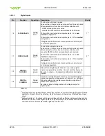
Command 

Acknowledgement 

(within 10ms after reception of 

command) 

Description 

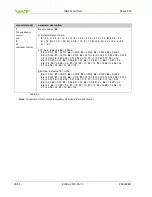
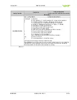
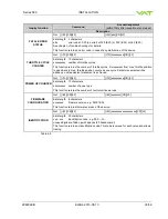
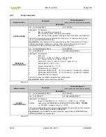
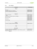
WARNINGS 

Get 

[i:51][CR][LF] 

[i:51][abcdefgh][CR][LF] 

data length  8 characters 
a  

0

 = no service required 


1

 = service request, it is indicated when the control unit detects that  


motor steps are apparently not effective. This may happen when the valve  


is heavily contaminated or the gate seal is heavily sticking. These ‚lost‘ steps 


are recognized and will be repeated to attempt target position in the short  


term. But in the medium term the valve requires cleaning or inspection. 

b  

0

 = LEARN data set present, 

1

 = LEARN data set not present 

c  

0

 = power failure battery ready 


1

 = power failure battery not ready 

d  

0

 = compressed air supply ok 


1

 = compressed air supply not ok 

efgh 

reserved, do not use 


This function returns warning information about the valve. If a warning is present 
countermeasure should be taken. Use RESET command to delete service request bit. 

Pay attention:

 Without LEARN the valve is not able to run pressure control 


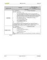
ERROR STATUS 

Get 

[i:52][CR][LF] 

[i:52][abcdefgh][CR][LF] 

data length  8 characters 
a  

reserved, do not use 

b  

1

 =  sensor 1 signal converter failure 

c   

reserved, do not use 

d  

1

 =  firmware memory failure 

efgh 

reserved, do not use 

This function returns an error code in case of any malfunction of the device otherwise 0 is 
returned. 

Table 4-8 


Summary of Contents for 590 Series

Page 1: ...on 2013 05 13 Variable leak valve DN 16 5 8 preliminary with integrated controller with RS232 interface Series 590 DN 16 mm I D 5 8 This manual is valid for the following product ordering number 59024...

Page 2: ...duplicated or distributed without written permission from VAT Offenders are liable to pay damages The original VAT firmware and updated state of the art versions of the VAT firmware are intended for u...

Page 3: ...oller 15 4 3 Electrical connection 16 4 3 1 Sensor supply concepts 17 4 3 2 Power and sensor connection 24 VDC sensors 17 4 3 2 1 Sensor power wiring via controller 17 4 3 2 2 Sensor power wiring exte...

Page 4: ...6 3 Errors 43 5 6 4 Safety mode 43 5 7 Operation under increased temperature 43 5 7 1 Bake out 43 5 8 Behavior during power up 44 5 9 Behavior during power failure 44 5 10 Trouble shooting 45 6 Mainte...

Page 5: ...cation number 1 2 Use of product Use product for clean and dry vacuum applications only Other applications are only allowed with the written permission of VAT 1 3 Used abbreviations Abbreviation Descr...

Page 6: ...ctor SENSOR Sensor input Signal input voltage Input resistance ADC resolution Sampling time 0 10 VDC Ri 100 k 0 23 mV 10 ms connector SENSOR Ambient temperature 0 C to 50 C max 35 C recommended Pressu...

Page 7: ...rate 60 Ch 1 Mounting position Any Process side materials body 1 4943 AISI 660 1 4404 AISI 316 L diaphragm 1 4310 AISI 301 gold plated Test pressure 1 bar Pressure range at 20 C UHV to 10 bar abs Dif...

Page 8: ...ion Operating Maintenance Instructions are an integral part of a comprehensive documentation belonging to a complete technical system They must be stored together with the other documentation and acce...

Page 9: ...2EB Edition 2013 05 13 9 56 2 3 Personnel qualifications WARNING Unqualified personnel Inappropriate handling may cause serious injury or property damage Only qualified personnel are allowed to carry...

Page 10: ...d mechanical position indicator Figure 3 1 3 2 Function The valve plate acts as a throttling element and varies the conductance of the valve opening Actuation is performed with a stepper motor and con...

Page 11: ...ntion that valve and flanges don t get damaged when the valve is lifting out of the box and handled afterwards NOTICE Contamination Plate and other parts of the valve must be protected from contaminat...

Page 12: ...ection Wrong connection may result in damage of controller or power supply Connect all cables exactly as shown in the following descriptions and schematics NOTICE Burned connector pins spark Connector...

Page 13: ...NSTALLATION 298292EB Edition 2013 05 13 13 56 4 2 1 Installation space condition Install the valve with integrated controller with space for dismantling and air circulation as shown in figure below 75...

Page 14: ...05 13 298292EB 4 2 2 Connection overview System M 3 4 5 7 8 2 1 9 6 1 Valve 2 Process chamber 3 Gas inlet 4 Controller 5 Pressure sensor 6 Sensor cable 7 Cable to remote control unit RS232 8 Cable to...

Page 15: ...rrect wiring 59024 GEGG 0001 supports 1 sensor 5 Connect valve to RS232 7 connector INTERFACE Refer to RS232 schematics for correct wiring 6 Connect power supply 8 to valve connector POWER Refer to ch...

Page 16: ...ng connection may result in damage of controller or power supply Connect all cables exactly as shown in the following descriptions and schematics NOTICE Burned connector pins spark Connector pins or e...

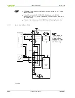
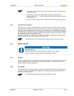
Page 17: ...ENSOR connector to supply 24 VDC sensors Refer to chapter Power and sensor connection 24 VDC sensors for schematic and correct wiring 4 3 2 Power and sensor connection 24 VDC sensors 4 3 2 1 Sensor po...

Page 18: ...y 24 GND at DB 9 male power connector and Sensors 24V 0V at DB 15 female sensor connector exactly as shown in the drawing above Connector Use only screws with 4 40 UNC thread for fastening the connect...

Page 19: ...mend using this only for setup testing and maintenance and not for permanent control Refer also to chapter Local Operation for details and to chapter Spare parts Accessories for ordering numbers of se...

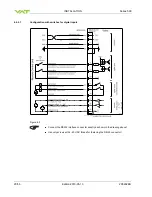
Page 20: ...on 2013 05 13 298292EB 4 4 2 1 Configuration with switches for digital inputs Figure 4 5 Connect the RS232 interface connector exactly as shown in the drawing above Use only screws with 4 40 UNC threa...

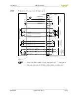
Page 21: ...on 2013 05 13 21 56 4 4 2 2 Configuration with voltage source for digital inputs Figure 4 6 Connect the RS232 interface connector exactly as shown in the drawing above Use only screws with 4 40 UNC th...

Page 22: ...ation The function is activated when optocoupler is off in inverted configuration Configuration can be done in local operation via service port or in remote operation 2 2 23 DIGITAL GROUND Digital gro...

Page 23: ...rn on external 24 VDC power supply of valve and external 15 VDC for sensor power supply if required Refer to chapter Behavior during power up for details 2 Interface configuration RS232 parameters and...

Page 24: ...ctionality of digital interlock inputs CLOSE VALVE and OPEN VALVE These may be configured as not inverted inverted or disabled Default is not inverted Refer also to chapter Digital inputs Pressure and...

Page 25: ...cdefgh configuring Control mode a s 02 s 02a switch to Control mode a without configuring s 02 Get i 02 get configuration actual Control mode i 02abcdefgh i 02a get configuration Control mode a i 02ab...

Page 26: ...0 024 12 0 032 13 0 042 14 0 056 15 0 075 16 0 10 17 0 13 18 0 18 19 0 24 20 0 32 21 0 42 22 0 56 23 0 75 24 1 0 25 1 3 26 1 8 27 2 4 28 3 2 29 4 2 30 5 6 31 7 5 32 10 33 13 34 18 35 24 36 32 37 42 3...

Page 27: ...rmance 2 Slow pressure response If the response to a set point change is slow the control speed can be increased by raising P Gain and I Gain 3 Fast pressure response with oscillations If the response...

Page 28: ...3 Control a typical pressure flow situation 4 Repeat from step 2 with slower valve speed until required response is achieved Local operation Control View Control Performance Analyzer or Service Box 2...

Page 29: ...rol is not selected HOLD Set H CR LF H CR LF This function stops the valve at the current position It is effective in PRESSURE CONTROL and POSITION CONTROL The function can be revoked by a POSITION CO...

Page 30: ...al input 9 INTERLOCK CLOSED by digital input C power failure D safety mode E fatal error read FATAL ERROR STATUS for details c 0 no warning 1 warning present read WARNINGS and ERROR STATUS for details...

Page 31: ...OPEN by digital input 9 INTERLOCK CLOSED by digital input C power failure D safety mode E fatal error read FATAL ERROR STATUS for details c 0 Power Failure Option PFO disabled 1 Power Failure Option...

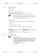
Page 32: ...cleaning or inspection b 0 LEARN data set present 1 LEARN data set not present c 0 power failure battery ready 1 power failure battery not ready d 0 compressed air supply ok 1 compressed air supply n...

Page 33: ...from max throttle position to open back to max throttle position counts as one cycle Partial movements will be added up until equivalent movement is achieved POWER UP COUNTER Get i 72 CR LF i 72 xxxxx...

Page 34: ...00k 2 2400 3 4800 4 9600 5 19 2k 6 38 4k 7 57 6k 8 115 2k b parity bit 0 even 1 odd 2 mark 3 space 4 no c data length 0 7 bit 1 8 bit d number of stop bits 0 1 1 2 e 0 reserved do not change f digital...

Page 35: ...0 0042 06 0 0056 07 0 0075 08 0 010 09 0 013 10 0 018 11 0 024 12 0 032 13 0 042 14 0 056 15 0 075 16 0 10 17 0 13 18 0 18 19 0 24 20 0 32 21 0 42 22 0 56 23 0 75 24 1 0 25 1 3 26 1 8 27 2 4 28 3 2 29...

Page 36: ...for reading xxxx valve speed 1 1000 1 min speed 1000 max speed This command allows changing the actuating speed of the valve plate Speed selection is effective for pressure control and position contr...

Page 37: ...R LF missing E 000011 CR LF Invalid number of characters between and CR LF E 000012 CR LF Unknown command E 000020 CR LF E 000021 CR LF Invalid value E 000022 CR LF E 000023 CR LF Value out of range E...

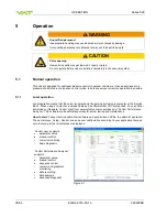
Page 38: ...valve is operated via the service port using a computer or the Service Box 2 When using a computer a service cable and a software from VAT are required You can either download our freeware Control Vie...

Page 39: ...g during remote control In case Control View or Control Performance Analyzer software is connected to valve make sure REMOTE button is pushed to enable for remote operation In case Service Box 2 is co...

Page 40: ...ifference is evaluated prior to operating in position control 5 5 Pressure control To prepare valve for PRESSURE CONTROL perform complete chapter Setup procedure The valve has parameters that may be m...

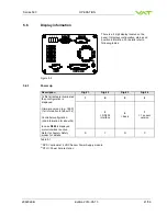
Page 41: ...on Digit 1 Digit 2 Digit 3 Digit 4 At first all dots are illuminated then configuration is displayed Firmware version e g 1E00 1st information for about 3s Controller configuration 2nd information for...

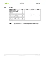
Page 42: ...Valve closed C Valve open O Closed open interlock Valve closed open by digital input I HOLD position frozen activated H Safety mode established Refer to chapter Safety mode for details D Power failure...

Page 43: ...splay shows INIT for a moment followed by SYNC When safety mode is entered from operation i e pressure control mode the unit will automatically switch to position control mode and remain at current po...

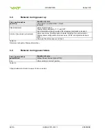
Page 44: ...eceived All other than closed not isolated Valve runs to max throttle position to detect limit stop for synchronization Display shows configuration of product resp SYNC until synchronization is done V...

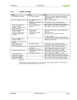
Page 45: ...CV CPA Service Box2 Display shows E 40 and position is 009999 fatal error motor driver failure detected Replace control and actuating unit according to chapter Maintenance procedures Display shows D...

Page 46: ...ct PRESSURE CONTROL mode Refer to chapter Pressure control for details Fixed PI done Perform Fixed PI Refer to chapter Setup procedure for details PRESSURE CONTROL not optimal Setup done completely Pe...

Page 47: ...intenance may only be carried out by the VAT service staff In exceptional cases the customer is allowed to carry out the maintenance but only with the prior consent of VAT Please contact one of our se...

Page 48: ...pairs may only be carried out by the VAT service staff In exceptional cases the customer is allowed to carry out the repairs but only with the prior consent of VAT Please contact one of our service ce...

Page 49: ...cribed work 8 1 Dismounting WARNING Harmful substances Risk of serious injury in case of contact with harmful substances Remove harmful substances e g toxic caustic or microbiological from the valve b...

Page 50: ...humidity between 10 and 70 temperature between 10 C and 50 C non condensing environment NOTICE Inappropriate packaging Product may get damaged if inappropriate packaging material is used Always use t...

Page 51: ...l packaging material and handle product with care When returning products to VAT please fill out the VAT form Declaration of Chemical Contamination of Vacuum Valves and Components and send it to VAT i...

Page 52: ...92EB 9 2 Transport NOTICE Inappropriate packaging Product may get damaged if inappropriate packaging material is used Always use original packaging material and handle product with care VAT disclaims...

Page 53: ...Series 590 DISPOSAL 298292EB Edition 2013 05 13 53 56 10 Disposal WARNING Harmful substances Environmental pollution Discard products and parts according to the local regulations...

Page 54: ...RE PARTS Series 590 54 56 Edition 2013 05 13 298292EB 11 Spare parts There are no spare parts defined Please contact one of our service centers You will find the addresses on our website www vatvalve...

Page 55: ...Series 590 APPENDIX 298292EB Edition 2013 05 13 55 56 12 Appendix...

Page 56: ...Series 590 56 56 Edition 2013 05 13 298292EB This Page Intentionally Left Blank...

Reviews: