background image


Installation, Operating & Maintenance Instructions 

Series 650 DN 350 (I.D. 14”), CC-Link


VAT Vakuumventile AG, CH-9469 Haag, Switzerland 

Tel +41 81 771 61 61   Fax +41 81 771 48 30   CH@vatvalve.com   www.vatvalve.com


286241EA


2010-10-11 

69/86 


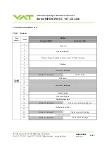
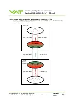
3.12.3 Communication and timing control between Master (PLC) and Station (Valve) 

See chapter: «OUTPUT Buffer» > «PING PONG TX-BIT» and «INPUT Buffer» > «PING PONG RX-BIT». 
For visual overview see the diagram below. 


CC

-L

in


CC-Link buffer 


Microcontroller 

Ping Pong Rx = Ping Pong Tx 

inverted 

Slave 

Station 

= Valve 

PLC 

Check if 

Ping pong Rx = Ping Pong Tx 

inverted 

CC-Link buffer 

MASTER 

Station = PLC 

Ping PongTx-bit 

Ping PongTx-bit 

Ping PongTx-bit 

Ping Pong Rx-bit 

Ping Pong Rx-bit 

Ping Pong Rx-bit 
 

output 

input 

output input 


St

at

io

n i

n

te

rn


M

ast

er


int

e

rn


Summary of Contents for 650 Series

Page 1: ... each product as per the label below or similar made in Switzerland Fabrication No 650 A Fabrication number sample picture Explanation of symbols Read declaration carefully before you start any other action Keep body parts and objects away from the valve opening Attention Hot surfaces do not touch Product is in conformity with EC guidelines if applicable Loaded springs and or air cushions are pote...

Page 2: ...ilms or any other reproduction processes nor may it be manipulated with electronic systems duplicated or distributed without written permission from VAT Offenders are liable to pay damages The original VAT firmware and updated state of the art versions of the VAT firmware are intended for use with VAT products The VAT firmware contains a limited time unlimited user license The VAT firmware may not...

Page 3: ...ntroduction 27 3 1 1 Individual valve control 28 3 1 2 Individual valve status 28 3 1 3 Freeze mode 28 3 1 4 Position offset 28 3 1 5 Local operation 29 3 1 6 Remote operation 29 3 1 7 Safety mode 30 3 1 8 Service indication 30 3 2 Operation under increased temperature 30 3 3 Behavior during power up 30 3 4 Behavior in case of power failure 31 3 5 Display information 32 3 5 1 CC Link LEDs 34 3 6 S...

Page 4: ...d Tel 41 81 771 61 61 Fax 41 81 771 48 30 CH vatvalve com www vatvalve com 286241EA 2010 10 11 4 86 4 Trouble shooting 71 4 1 Additional CC Link warning 73 5 Maintenance repairs 74 5 1 Maintenance procedures 75 5 2 Option board 81 5 2 1 Durability of power fail battery 81 5 2 2 Retrofit replacement procedure 82 6 Warranty 86 ...

Page 5: ...1000 mA max connector SENSOR Sensor input Signal input voltage Input resistance ADC resolution Sampling time 0 10 VDC Ri 100 kΩ linear to pressure 0 23 mV 10 ms connector SENSOR Digital inputs 3 24 VDC max connector INTERFACE Digital outputs 3 Input voltage Input current Breaking capacity 70 VDC or 70 V peak max 0 5 ADC or 0 5 A peak max 10 W max connector INTERFACE Analog outputs 3 optional 0 10 ...

Page 6: ...d under clean conditions 1 000 000 unheated and under clean conditions Admissible operating temperature 10 C to 150 C Mounting position horizontally only valve seat to face chamber is recommended Wetted materials body Aluminium AA6082 3 2315 pendulum plate Aluminium AA6082 3 2315 sealing ring Aluminium AA6082 3 2315 3 2315 AA6082 1 4306 304L Other parts Stainless steel 316L 1 4404 or 1 4435 1 4122...

Page 7: ...lifting The attachment points are indicated on the dimensional drawing of the specific valve part number available on request Never lay the valve down with control and actuating unit downwards as it may be damaged 2 2 Installation into the system Connectors at controller panel Connection overview Fingers and objects must be kept out of the valve opening and away from moving parts The valve plate s...

Page 8: ...or slightly oiled air IN OUT connections are 1 8 ISO NPT internal threads 3 Install the ground connection cable at controller Refer to Electrical connection 4 Install pressure sensor s 2 according to the recommendations of the sensor manufacturer and directives given under Requirements to sensor connection 5 Connect sensor cable 3 to sensor s and then to Master valve connector SENSOR Refer to chap...

Page 9: ...could be connected to the vacuum line see Figure 2 below 11 These valves may optionally be equipped with a heating device Connect VAT heating device according to manual of respective heating device 12 Perform Setup procedure to prepare valve cluster for operation Note Without performing the setup procedure the valve cluster will not be able to do pressure control Fig 1 Fig 2 2 3 Tightening torque ...

Page 10: ... adapted Please review design guidelines for Helicoil Screw connections and make sure that screws in use are capable to withstand applied torques are appropriate for the application and are not too long Too long screws may damage the valve the immersion depth should not exceed hole depth 1 mm Tighten mounting screws of the flanges uniformly in crosswise order Observe the maximum torque levels in t...

Page 11: ...unting screws is min 1 x thread diameter Please contact VAT for more information 2 5 Requirements to sensor connection To achieve fast and accurate pressure control a fast sensor response is required Sensor response time 50ms The sensor is normally connected to the chamber by a pipe To maintain that the response time is not degraded by this connection it needs to meet the following requirements In...

Page 12: ...B2 min d1 d2 copper tinned 200 mm 25 mm 25 mm 4 5 mm customized Note Connection plates of ground strap must be total plane for a good electrical contact Note The connection point at chassis PE must be blank metal not coated It is also possible to connect the ground strap at system chamber if it is well connected to PE Note Avoid low chassis cross section to the system PE connection Min same cross ...

Page 13: ...WER connector is feed through to SENSOR connector to supply 24 VDC sensors Refer to chapter Power and sensor connection 24 VDC sensors for schematic and correct wiring External 24 VDC supplied to POWER connector is converted into 15 VDC by the valve internal SPS and supplied to SENSOR connector to supply 15 VDC sensors Refer to chapter Power and sensor connection 15 VDC sensors with optional SPS m...

Page 14: ... V 650 W versions only Note Use shielded sensor cable s Keep cable as short as possible but locate it away from noise sources Connect the 15 VDC sensors at DB 15 female sensor connector exactly as shown in the drawing above Do not connect other pins that may damage sensor power supply or controller Connector Use only screws with 4 40UNC thread for fastening the connectors Pins 4 and 8 must be brid...

Page 15: ... com 286241EA 2010 10 11 15 86 2 6 4 Power connection for Slave valve only 650 S or valves configured as slave Note Do not connect other pins as shown above that may damage power supply or controller Connector Use only screws with 4 40UNC thread for fastening the connectors Pins 4 and 8 must be bridged for operation An optional switch would allow for motor interlock to prevent valve from moving ...

Page 16: ...stallation example PE Protective Earth Connector housing PE PE Internal connection between SLD and FG Note The valve can be defined as first station stations between first and last or last station If the valve at first or last station TR must be installed between 1 DA and 2 DB Note The station type for VAT valves are Version 2 Remote Device Station TR Terminal resister Must be compatible to used C...

Page 17: ... connector Description Required tool 1 Remove COMBICOM connector A at valve controller sample picture 2 Prepare all parts of connector for installation Note All parts of connector are supplemented in a plastic bag 407612 except COMBICOM connector from valve controller 2 6 5 3 CC Link connector overview A COMBICON D Strain relief screw for shield mesh and cable B CC Link wires E Connector housing V...

Page 18: ...uired tool 3 Remove the cable coat carefully Cable Pos A x about 30mm Cable Pos B x about 40mm Note Pos see step 8 Knife 4 Cut off the shield wire Side cutting pliers 5 Cut off the aluminum shield and remove it Side cutting pliers 6 Cut off the plastic and remove it Note Take care to the wires Do not damage the isolation of wires Side cutting pliers 7 Cut off the shield wires about 15mm 8 Separate...

Page 19: ...fully about 5mm Wire strippers 10 Insert the cable s at connector hosing as shown in the pictures see also chapter CC Link connector Note If valve in CC Link network is at first or last station install the CC Link cable at position A and close B with blind plug C If valve in CC Link network at stations install the CC Link cables at position A and B 11 Fasten the strain relief screw until the cable...

Page 20: ...e If cable at pos A first or last station install TR between 1 and 2 1 x blue to 1 1 x white to 2 1 x yellow to 3 If cables at pos A B stations install 2 x blue to 1 2 x white to 2 2x yellow to 3 Screw driver size 1 13 Close the cover of connector and fasten the screws a little Pozidriv screw driver size 2 14 Connect the connector and fasten it with the screws at controller sample picture Allen Wr...

Page 21: ...8 with special VAT housing PIN interface connector Signal Color of isolator CC Link wires Comment 1 DA Blue Positive RS485 RxD TxD 2 DB White Negative RS485 RxD TxD 3 DG Yellow Signal Ground 4 SLD Cable Shield 5 FG Functional Ground The CC Link interface is galvanic isolated from control unit 2 6 5 5 CC Link network and cable Note For detail information about CC Link cable wiring and TR refer to C...

Page 22: ...for remote operation by means of a command set based on the CC Link protocol In addition there is a digital input and a digital output Digital input may only be operated by a switch Active digital input has higher priority than CC Link commands higher priority than freeze mode higher priority than Local commands Configuration with switch for digital input Note Do not connect other pins than indica...

Page 23: ...O for details about input circuit 2 Highest priority is 1 Functions with lower priorities will not be effective as long as higher priority functions are active The digital input has higher priority than all CC Link and Local commands and higher priority than freeze mode CC Link Local commands and freeze mode will not be accepted while digital input is active 2 6 8 Digital output Pin Function Signa...

Page 24: ...1 24 86 2 6 10 Valve cluster connection The valve cluster uses a two wire bus for the inter communication between the Master and the Slave valves The valves are connected in a daisy chain and the bus must be terminated on both sides by a 120Ω resistor that can be set in the link adapter for the valve refer to chapter 2 6 10 1 Link adapter 120Ω terminator category 5 link cable 120Ω terminator valve...

Page 25: ...ventile AG CH 9469 Haag Switzerland Tel 41 81 771 61 61 Fax 41 81 771 48 30 CH vatvalve com www vatvalve com 286241EA 2010 10 11 25 86 2 6 10 1 Link adapter Link adapter 2x RJ45 jack female 1x Service port Inside view with terminating resistor Factory default setting Terminating resistor OFF ...

Page 26: ...A 2010 10 11 26 86 Setting for first and last valve in the chain Terminating resistor ON 2 6 10 2 Link cable RJ45 pinning active pins 4 and 5 Pin Description 1 not used 2 not used 3 not used 4 Data 5 Data 6 not used 7 not used 8 not used VAT recommends a cable with the following specification Standard patch cable Category 5 or higher Double ended with shielded RJ45 connector Straight through conne...

Page 27: ...communication between the Master and the Slave valves The Master valve is taking care of the pressure control while the Slave valves are following the Master valves plate position It can be operated in pressure control mode or in position control mode In both cases local or remote operation is possible Therefore the host system mainly communicates with the Master valve The Master valve then takes ...

Page 28: ...S bitmap for details 3 1 3 Freeze mode This mode enables an individual valve to be controlled independent of the valve cluster As soon as a valve is set to Freeze mode freeze it will remain in the last position it received from the Master valve before it was frozen Now it is listening to commands addressed directly to it Refer to chapter OUTPUT Buffer Master PLC Details CLUSTER VALVE FREEZE CONTRO...

Page 29: ... monitoring basic diagnostic Control Performance Analyzer supports parameter setup manual control sequence control numeric and graphical monitoring data recording data analysis advanced diagnostic When communication to service port is interrupted the valve will change to remote operation So when service cable will be disconnected or software will be shut down the valve returns automatically to rem...

Page 30: ...hen the valve unit is heavily contaminated These lost steps are recognized and will be repeated to attempt target position in the short term But in the medium term the valve unit requires cleaning or inspection Service request SR would be indicated on the display or could be read via remote operation Refer to Display information for details 3 2 Operation under increased temperature Hot valve Heate...

Page 31: ...case of power failure Reaction of valve Valve position before power failure With Power Failure Option PFO 650 H 650 C 650 U 650 W Closed isolated Valve open or in any intermediate position Valve will close or open depending on valve configuration Default is close Display indicates F Provided that battery pack of the VAT controller is charged Charging time after power up is 2 minutes max All parame...

Page 32: ...inated then configuration is displayed Firmware version e g 1E00 1 st information for about 2s Controller configuration 2 nd information for about 2s In case D C or D999 is displayed motor interlock is active Refer to Safety mode for details If valve is closed isolated display shows alternately C C and INIT Synchronization will be done when first movement command is received A No or unknown busmod...

Page 33: ... Closed open interlock Valve closed open by digital input I HOLD position frozen activated H ZERO running Z LEARN running L Safety mode established Refer to Safety mode for details D Power failure F 0 100 valve position 0 closed 100 open Service request 1 S R Cluster address information MA Master SL Slave 0 FEhex cluster address Freeze mode FROZ valve frozen Errors Description Digit 1 Digit 2 Digi...

Page 34: ... Link LEDs Item 1 Error LED 2 CC Link Interface connector 3 Run LED Run LED 3 State Meaning Off No network participation timeout status no power Green Participating normal operation Red Major fault FATAL error Error LED 1 State Meaning Off No error detected no power Red Major fault Exception or FATAL event Red flickering CRC error temporary flickering Red flashing Station Number or Baud rate has c...

Page 35: ...ngs mode Refer to chapter CC Link configuration for details Master 4 Valve and sensor configuration Basic configurations of the Master valve must be adapted according to application needs Refer to chapter Valve and sensor configuration for details Master Slave 5 ZERO Compensation of the sensor offset voltage Refer to chapter ZERO for details Master 6 LEARN Determination of the vacuum system charac...

Page 36: ...650 DN 350 I D 14 CC Link VAT Vakuumventile AG CH 9469 Haag Switzerland Tel 41 81 771 61 61 Fax 41 81 771 48 30 CH vatvalve com www vatvalve com 286241EA 2010 10 11 36 86 3 6 1 1 Address setting via graphical interface SETUP CLUSTER Master valve Slave valve ...

Page 37: ...ge s 10 Command header none a Cluster address high byte in hexadecimal code 0 F b Cluster address low byte in hexadecimal code 0 F c Number of valves high byte in hexadecimal code Master only 0 F d Number of valves low byte in hexadecimal code Master only 0 F Command examples for Master valve Command s 1000120000 CR LF Answer x 10aaaaaabbbbbbbbccccccccddddefghhiiiikl CR LF Description Address allo...

Page 38: ...s allocation Each valve connected to the valve cluster system must have its unique cluster address It is possible to address 255 cluster valves The address allocation is as follows Master valve 00 Slave valves 01 FEhex Note If there only one Slave valve the adress must be 01 If there are more Slave valves they have to be addressed from 01 02 03 and so on without gap Note The device address informa...

Page 39: ...order without duplication must be used when assigning stations to the CC Link network The station number can be configured by Control View Control Performance Analyzer Universal Hyper Terminal or Service Box 2 The set command is s 25xxx00000 The xxx value is the station number Valid range is 001 to 064 The get command is i 25 The answer returns the node address Æ i 25xxx00000 The xxx value is the ...

Page 40: ...n rate 000 156 kbps 001 625 kbps 002 2 5 Mbps 003 5 Mbps 004 10 Mbps 3 Operational settings mode The operational settings mode defines the following CC Link parameters CC Link version Number of occupied stations The number of stations occupying one stations worth of memory area used by a single slave station in a network Extended cyclic settings In the extended cyclic transmission only Ver 2 the e...

Page 41: ...ult 0 xx signal number in the buffer xx Value 00 Pressure 01 Pressure sensor 1 02 Pressure sensor 2 optional only in case of 2 sensor version 03 Position 04 Not used reserved 05 Cluster valve position 06 Pressure setpoint 07 Position setpoint 08 Not used reserved 09 Not used reserved 10 Not used reserved 11 Cluster valve freeze position setpoint The get command is i 23xx The answer returns the dat...

Page 42: ...g point entry with a point and for negative values possible xx signal number in the buffer Default range Min Max range xx Value Default lower scale value Default upper scale value Min lower scale vlaue Max upper scale value 00 Pressure 0 1 000 000 1 000 000 1 000 000 01 Not used reserved 02 Not used reserved 03 Position 0 100 000 1 000 000 1 000 000 04 Not used reserved 05 Cluster valve position 0...

Page 43: ...n the memory are out of range or the rule above is broken the default values are taken In this case the get command i 24 add a string False Example s 24031234 56to7890 Æ set the range of position from 1234 56 closed position to 7890 opened position Example s 24000to100 75 Æ set the range of pressure from 0 0 V to 100 75 10 V Example s 2407 10 5to20 5 Æ set the range of Position setpoint from 10 5 ...

Page 44: ...a sheet Set on Master valve only o Slave offline default setting refer to individual product data sheet Set on Slave valves only ZERO function This may be disabled or enabled Default is enabled Refer also to ZERO Local operation Control View or Control Performance Analyzer Remote operation 1 Do power up configuration in menu Setup Valve 2 Do power fail configuration in menu Setup Valve 3 Do networ...

Page 45: ...the configuration s 04abcdefgh CR LF to read the configuration i 04 CR LF Note Each element is separated with square brackets for clarity Square brackets are not part of command syntax All elements are ASCII characters There are no spaces between the elements necessary Command is case sensitive abcde reserved do not change f 0 valve will close 1 valve will open 2 valve no change gh reserved do not...

Page 46: ...r or Service Box 2 Remote operation Refer to chapter OUTPUT Buffer GENERAL CONTROL SETPOINT for details 1 Wait until process chamber is evacuated and sensor signal is not shifting anymore 2 In OUTPUT Buffer GENERAL CONTROL SETPOINT set ZERO value 1 only short impulse ca 1sec Go to menu Zero ZERO and follow instructions 3 Wait until ZERO EXECUTED value 1 see INPUT Buffer Note Do not perform ZERO as...

Page 47: ...sed to adapt the PID parameters The data table is stored in the device memory which is power fail save The data table can be up downloaded via Control Performance Analyzer software or remote interface Due to encoding the data may not be interpreted directly By an OPEN VALVE CLOSE VALVE POSITION CONTROL or PRESSURE CONTROL command the routine will be interrupted Local operation Control View Control...

Page 48: ...flow for learn mbar l s pSFS sensor full scale pressure mbar Cmin min controllable conductance of valve l s refer to Technical data n number of valves in valve cluster used during pressure control qL 39 4 pSFS Cmin n qL gasflow for learn sccm pSFS sensor full scale pressure Torr Cmin min controllable conductance of valve l s refer to Technical data n number of valves in valve cluster used during p...

Page 49: ...ODE SETPOINT 4 Select Position value 2 3 10 Pressure control To prepare valve for PRESSURE CONTROL perform complete Setup procedure The valve has parameters that may be modified to tune pressure control performance Refer to Tuning of control performance The included PID controller controls the chamber pressure according to the pressure setpoint by means of the valve position The PID controller wor...

Page 50: ...y below Strictly keep the procedure order Required information for support Go to Tools Create Diagnostic File in Control View resp Control Performance Analyzer and save file Pressure flow gas conditions to be controlled Chamber volume Pumping speed l s and pump type e g turbo pump System description Problem description Send diagnostic file with and all required information to tuning support vat ch...

Page 51: ...n menu Setup Control Parameter Note It s not possible to do Gain factor adjustment via CC Link 3 10 1 2 Sensor delay adjustment Sensor delay adjustment effects Stability Default value is 0 Adjustment range is from 0 to 1 0s Pipes and orifices for sensor attachment delay response time and so badly impact pressure control stability By adapting this parameter to the approximate delay time stability p...

Page 52: ... depending on units you are familiar with t Setpoint Ramp Adjustment procedure 1 Start with optimal gain factor and sensor delay time according to preceding tuning steps 2 Control a typical pressure flow situation 3 Control a lower pressure 4 Repeat from step 2 with longer setpoint ramps until best response is achieved 5 Verify pressure control response for a setpoint raise situation Note In case ...

Page 53: ...te Normally best pressure control response is achieved with max valve speed In particular applications it may be of advantage to have a slower valve response Note OPEN and CLOSE are always done with max speed Adjustment procedure 1 Use optimal gain factor sensor delay time and setpoint ramp according to preceding tuning steps 2 Open valve 3 Control a typical pressure flow situation 4 Repeat from s...

Page 54: ...bit FIELDBUS DATA VALID 1 in the INPUT buffer GENERAL STATUS The CC Link Network failure is independent of the CC Link handshaking That means the Network failure is inactive if the handshaking is not done yet Procedure 1 If the network parameter are correct the slave station will set the bit Initial data processing request flag 2 The master have to answer the request with the bit Initial data proc...

Page 55: ... RY m n 6 RX m n 7 Reserved RY m n 7 Reserved RX m n 8 Initial data processing request flag RY m n 8 Initial data processing complete flag RX m n 9 Initial data setting complete flag RY m n 9 Initial data setting request flag RX m n A Error status flag RY m n A Error reset request flag RX m n B Remote READY RY m n B RX m n C RY m n C RX m n D RY m n D RX m n E RY m n E RX m n F Reserved RY m n F R...

Page 56: ...gram sends an answer to the VAT CC Link station which return a Remote READY flag It is important to correct register address is used In this example the address for this slave station valve starts at 1000 hex So m 100 see capture Location of the handshaking bits The Operational setting mode of the slave is 4 therefore n D Table 1 said RX m n 8 for the location of the Initial data processing reques...

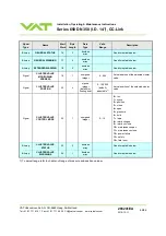
Page 57: ...e least significant byte LSB 3 12 1 OUTPUT Buffer Master PLC 3 12 1 1 Overview Buffer Data model Index Contents MSB Contents LSB 0 1 Pressure setpoint 2 3 Position setpoint 4 5 6 7 8 9 Not used reserved 10 Not used reserved Control mode setpoint 11 General control setpoint 12 13 14 15 Not used reserved 16 17 Cluster valve freeze position setpoint 18 Not used reserved Cluster valve freeze address s...

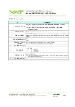
Page 58: ...E SETPOINT 3 Close only 650 Signal CONTROL MODE SETPOINT 10 1 unsigned integer 2 7 2 Position Position control mode 3 Close The valve is closed 4 Open The valve is opened 5 Pressure Pressure control mode 6 Hold Valve is kept in current position only valid in CONTROL MODE position and pressure 7 Learn Valve starts the internal learn procedure Bitmap GENERAL CONTROL SETPOINT 11 2 boolean array See b...

Page 59: ...ation 1 ZERO adjust the actual pressure signal is set to internal pressure 0 The valid range for adjustment is limited to 1 4V 1 4 Otherwise the sensor must be adjusted 1 NOT USED reserved 2 PING PONG TX BIT PING PONG TX BIT transmitted from the master PLC is used to check the loop master PLC VAT station See chapter 3 11 9 Communication and timing control between Master PLC and Station Valve 3 NOT...

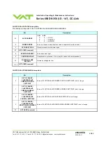
Page 60: ... valve is in control mode position 1 Chosen cluster valve is in control mode close Note Only valid if bit FREEZE DATA VALID is set 2 FREEZE DATA VALID Corresponds to Signal CLUSTER VALVE FREEZE ADDRESS SETPOINT Bit FREEZE CONTROL Bit FREEZE CONTROL MODE Signal CLUSTER VALVE FREEZE POSITION SETPOINT 0 Data above are not valid and will not have an effect on the valve 1 Data above are valid and will ...

Page 61: ...ol mode position 3 Set bit CLUSTER VALVE FREEZE POSITION SETPOINT max position default 100 000 4 Set bit FREEZE CONTROL 1 enable freeze mode for this cluster valve 5 Activate the values by setting the following bit Set bit FREEZE DATA VALID Example for individual valve monitoring Task Select the cluster valve with address 3 to monitor 1 Set signal CLUSTER VALVE MONITORING ADDRESS SETPOINT 3 in OUT...

Page 62: ...ents MSB Contents LSB 0 1 Pressure 2 3 Pressure Sensor 1 4 5 Pressure Sensor 2 optional only in case of 2 sensor version 6 7 Position 8 9 Not used reserved 10 Not used reserved Control mode 11 Fatal error 12 13 14 15 Not used reserved 16 General status 17 General warnings 18 Extended warnings 19 Not used reserved Cluster valve monitoring address 20 21 Cluster valve position 22 Not used reserved Cl...

Page 63: ... sensor 10 Volt equals to 1 000 000 Signal PRESSURE SENSOR 2 4 4 signed integer default or floating point 270000 1 230 000 default 2 7V 12 3V sensor signal adjustable1 Optional only in case of 2 sensor version In case of default valid range Physical full scale value of the sensor 10 Volt equals to 1 000 000 Signal POSITION 6 4 signed integer default or floating point 0 100 000 default adjustable1 ...

Page 64: ... VALVE MONITORING ADDRESS 19 1 unsigned integer 0 254 Actual address of the selected cluster valve Signal CLUSTER VALVE POSITION 20 4 signed integer default or floating point 0 100 000 default adjustable1 Actual position of the selected cluster valve Signal CLUSTER VALVE CONTROL MODE 22 1 unsigned integer 0 14 0 init 1 synch 2 position 3 close 4 open 5 pressure 6 hold 7 learn 8 interlock open 9 in...

Page 65: ...sing Complete 1 ZERO EXECUTED ZERO successful executed active for 2 seconds 2 PING PONG RX BIT PING PONG RX BIT is inverted and transmitted back to the fieldbus master PLC See chapter 3 1 3 Communication and timing control between Master PLC and Station Valve 3 PRESSURE SIMULATION 0 off 1 on 4 PRESSURE SETPOINT REACHED 0 The actual pressure is not within 2 of the pressure setpoint 1 The actual pre...

Page 66: ...ot present Learn required for adaptive pressure control 2 COMPRESSED AIR compressed air pressure 4 bar only for valves with compressed air 3 POWER FAILURE BATTERY Not ready voltage too low 4 SENSOR OVERLAPPING Sensor deviation between sensor 1 and sensor 2 10 5 NOT USED reserved 6 CLUSTER SLAVE VALVES OFFLINE One or more cluster slaves are offline 7 9 NOT USED reserved 10 SENSOR MEASUREMENT UNIT F...

Page 67: ... CONTROL MODE SETPOINT for example control mode is interlock or fatal error 2 ZERO DISABLED Using zero function not possible 3 PFO DEACTIVATED Power Failure Option is deactivated 4 NOT USED reserved 5 OUT OF RANGE PRESSURE SETPOINT Value of PRESSURE SETPOINT is out of range 6 OUT OF RANGE POSITION SETPOINT Value of POSITION SETPOINT is out of range 7 9 NOT USED reserved 10 OUT OF RANGE CONTROL MOD...

Page 68: ... USED reserved 8 SERVICE REQUEST Valve movement tight 9 COMPRESSED AIR Compressed air pressure 4 bar only for valves with compressed air 10 POWER FAILURE BATTERY Not ready voltage too low 11 15 NOT USED reserved CLUSTER VALVE WARNINGS bitmap table Bit Description 0 OUT OF RANGE CLUSTER VALVE FREEZE POSITION SETPOINT Value of CLUSTER VALVE FREEZE POSITION SETPOINT is out of range 1 OUT OF RANGE CLU...

Page 69: ...aster PLC and Station Valve See chapter OUTPUT Buffer PING PONG TX BIT and INPUT Buffer PING PONG RX BIT For visual overview see the diagram below CC Link CC Link buffer Microcontroller Ping Pong Rx Ping Pong Tx inverted Slave Station Valve PLC Check if Ping pong Rx Ping Pong Tx inverted CC Link buffer MASTER Station PLC Ping PongTx bit Ping PongTx bit Ping PongTx bit Ping Pong Rx bit Ping Pong Rx...

Page 70: ...RESSURE and SENSOR READING allocation Example of PRESSURE and SENSOR READING allocation Above picture shows a 2 sensor system In this configuration sensor 2 covers low range 100 mTorr and sensor 1 covers high range 1 Torr Switchover between sensors is done automatically according to Pressure control operation with 2 sensors 0 10V High range sensor Low range sensor 0 10V SENSOR 1 100 mTorr 1 Torr 0...

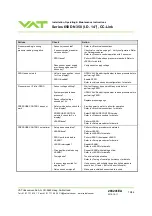
Page 71: ...d or replace gate seal according to Maintenance procedures CLOSE VALVE does not work Safety mode active check for D on display Maintenance mode active Provide power to motor to allow for operation Refer to Electrical connection for details Refer to Display shows M C in this table OPEN VALVE does not work Safety mode active check for D on display Maintenance mode active Provide power to motor to al...

Page 72: ...ystem pumped to base pressure OPEN VALVE and bring chamber to base pressure before performing ZERO Pressure is not 0 after ZERO Sensor offset voltage exceeds 1 4V Replace pressure gauge Safety mode active check for D on display Provide power to motor to allow for operation Refer to Electrical connection for details PRESSURE CONTROL selected check for P on display Select PRESSURE CONTROL mode Refer...

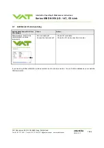
Page 73: ...241EA 2010 10 11 73 86 4 1 Additional CC Link warning Failure detection with CPA or CV software Check Action Network failure No CC Link communication is active warning 8 CC Link cable ok Connection to master ok Check CC Link cable Check the CC Link connection to master If you need any further information please contact one of our service centers You can find the addresses on our website http www v...

Page 74: ...performed by the customer or has to be carried out by VAT The fabrication number on the valve made in Switzerland Fabrication No A Fabrication number has always to be specified All supplies e g compressed air electrical power must be disconnected for removal installation of the valve from into the system Even with disconnected supply loaded springs and or air cushions in cylinders can be potential...

Page 75: ...er increased temperature In this case grease will separate to PTFE and oil The oil may flow and contaminate the valve parts VAT can give the following recommendations for preventive maintenance unheated heated 80 C heated 80 C isolation seals gate and body seal of sealing ring 200 000 cycles 6 months but max 200 000 cycles 3 months but max 200 000 cycles actuator shaft seals 1 000 000 cycles 6 mon...

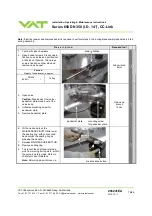
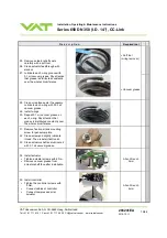
Page 76: ...fixation on other side and remove valve bonnet Caution Weight of valve bonnet is approx DN350 65051 15 0 kg snap in fixation Allen wrench 8mm 3 Open valve Caution Stand away from valve pendulum plate moves out of the valve body 4 Unfasten mounting screw for pendulum plate 5 Remove pendulum plate pendulum plate mounting screw for pendulum plate Open end wrench 13mm 6 With one hand press the MAINTEN...

Page 77: ...expose seals actuator and retaining pin feedthroughs to air stream 13 Clean or replace gate seal if necessary Install gate o ring to sealing ring without grease body seal Valve size Quantity of grease ml 14 Clean or replace body seal if necessary Lubricate body o ring with the quantity of vacuum grease listed in the table to the right 350 0 4 15 Install body o ring into sealing ring Valve size Qua...

Page 78: ... 20 Move the valve to position 50 half opened This is necessary in order to dismount the actuator See step 24 21 Disable PFO option feature via Power Fail Status in menu System of CV or CPA software and turn off the power CV software CPA software or Service Box 2 22 Disconnect 24VDC power Wait for 60s then disconnect cable and compressed air from valve actuator 23 Unfasten all 4 controller screws ...

Page 79: ...Vacuum grease 28 Clean or replace seals if necessary Lubricate each o ring with 0 05 ml vacuum grease 29 Install o rings 30 Deposit 0 1 ml vacuum grease on each o ring Pay attention that grease is distributed constantly over the whole circumference 31 Remove fixation kit and mounting screw for pendulum plate 32 Clean screw and slightly lubricate thread Then reinstall fixation kit 33 Clean actuator...

Page 80: ... done either visual or by measurement When the valve is mounted to a tool the bonnet has to be removed and the center position can be measured by a depth gauge see picture If the centering or distance is not correct proceed with point 39 D 350 59 0 0 5 39 If necessary adjust pendulum plate a Move pendulum plate a little towards open e g position 1 of full stroke b Use adjustment screw at flange si...

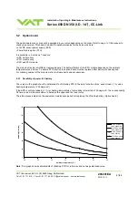
Page 81: ...e PFO function the option board must be replaced after battery life has expired For ordering number of the modules refer to Spare parts and accessories 5 2 1 Durability of power fail battery The curves in the graph show the estimated life of UltraCap PFO in the worst condition max sensor load 1 A valve heating temperature 150 degree C If the SPS is not fully loaded 1 A or heating temperature of va...

Page 82: ...D Precaution All work on the control and actuating unit has to be done under ESD protected environment to prevent electronic components from damage Top view on control and actuating unit with panel removed Note All boards have a fixed position into control and actuating unit It is not possible to fit a board in other position as shown in picture above Do not try out other positions that may be des...

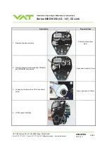
Page 83: ...61 61 Fax 41 81 771 48 30 CH vatvalve com www vatvalve com 286241EA 2010 10 11 83 86 Description Required tool 1 Remove the panel screws Pozidriv screw driver size 1 2 Remove female screw locks from POWER and SENSOR connectors Open end wrench 4 5 mm 3 Loosen and remove the LOCIC connector screw Open end wrench 10mm 4 Lift the panel carefully ...

Page 84: ... Pull out the option board a little 6 Push the connector release 1 a little down and disconnect fan cable 2 from option board 7 Remove the interface board or replace it if existing master board is defect 8 Remove the master board or replace it if existing interface board is defect 9 Remove the option board or replace it if existing option board is defect 10 Insert all boards in reverse order as th...

Page 85: ...1 81 771 48 30 CH vatvalve com www vatvalve com 286241EA 2010 10 11 85 86 Description Required tool 11 Reassemble the controller panel see steps 6 3 Open end wrench 10mm 12 Tighten female screw locks from POWER and SENSOR connectors with 1 1 Nm see step 2 Open end wrench 4 5 mm 13 Tighten panel screws with 1 1 Nm see step 1 Pozidriv screw driver size 1 ...

Page 86: ...r expense whether consequential special incidental direct or otherwise caused by arising out of or connected with the manufacture delivery including any delay in or failure to deliver packaging storage or use of any product sold or delivered by VAT shall fail to conform to the foregoing warranty or to the description thereof contained herein the purchaser thereof as its exclusive remedy shall upon...

Reviews: