background image


Vatech A9 (PHT-30CSS) 

Technical manual   


VDH-TeM-098


131  / 214


COPYRIGHT© 2020 VATECH

.


ALL RIGHTS RESERVED


6.2. Right and Left Pin Distance Calibration 


• 

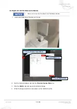
Make sure to move the Chin Block to the PANO Mode Position.


1.  Attach the PANO BALL Phantom on Chinrest. 


2.  Run the Console Software and click the 

Phantom Capture Mode

 icon. 

3.  Click the 

PANO

 mode and acquire the phantom image.   

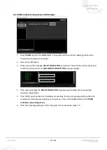
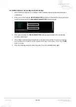
4.  When the image acquisition is completed, run the VAKCAP.exe file. 


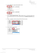
1. Click the 

Phantom Capture Mode

2. Click the 

PANO

 mode. 

3. Click the 

Capture

 buton. 

Summary of Contents for A9

Page 1: ...Vatech A9 PHT 30CSS Technical manual VDH TeM 085 0 172 COPYRIGHT 2020 VATECH ALL RIGHTS RESERVED...

Page 2: ...y repair but maintenance We strongly recommend familiarizing yourself with this Technical manual to carry out the necessary information on the VATECH equipment The information contained in this Techni...

Page 3: ...onnection Diagram 27 3 2 Main MCU and SENSOR Connection Diagram 30 3 3 Sensor Part Connection Diagram 32 3 4 CEPH SENSOR Part Connection Diagram 32 3 5 Connection Diagram Total assembly 33 4 Disassemb...

Page 4: ...al Resolution MTF standards 100 1 2 Phantom Specification 100 1 3 Test Method 101 1 4 Test Result 101 2 Contrast evaluation 102 2 1 Contrast standards 102 2 2 Phantom Specification 102 2 3 Test Method...

Page 5: ...ation 113 2 Equipment default values 113 2 1 Bite location PANO mode 113 3 PANO Sensor Calibration 114 3 1 PANO Sensor Calibration Standard 114 3 2 Before PANO sensor calibration 114 3 3 PANO sensor s...

Page 6: ...ation 140 4 1 Homogeneity standards 140 4 2 Phantom Specification 140 4 3 Test Method 140 4 4 Test Result 140 5 Collimator Alignment Evaluation 141 5 1 Collimator Alignment Standard 141 5 2 Test Metho...

Page 7: ...Test Method 168 2 4 Test Result 168 3 Line Pair Resolution Evaluation 169 3 1 Noise standards 169 3 2 Phantom Specification 169 3 3 Test Method 169 3 4 Test Result 169 4 Low Contrast Resolution evalua...

Page 8: ...unction 197 3 1 When exposure the PANO CEPH in Console Software 197 3 2 Remote exposure sequence when acquiring the Bright Calibration 197 3 3 TUTS Test 197 3 4 XTST Test 197 4 Error Message List 198...

Page 9: ...aused by unauthorized engineers To effectively describe safety information the following signs are used in this manual WARNING Critical application information that could result in critically severe i...

Page 10: ...ipment with enough experience Only VATECH authorized operator can handle the electrical circuit board and an understanding of the electric and electrical system is required Be able to recognize operat...

Page 11: ...MCU boards are electrically sensitive that operators need to wear shielding gloves while operating The only part that can be replaced by the users is the input fuses Check if the fuses comply with the...

Page 12: ...nt must be housed inside an X ray shielded room Or operators should use a shielding plate to minimize radiation exposure while operating the system The equipment exposes radioactive rays and only spec...

Page 13: ...1 Do the equipment power and PC condition work fine 2 Is the power off before the equipment repair begins 3 Is the voltage range indicated back of the equipment observed properly 4 Is the equipment gr...

Page 14: ...Vatech A9 PHT 30CSS Technical manual VDH TeM 098 13 214 COPYRIGHT 2020 VATECH ALL RIGHTS RESERVED Chapter 1 Hardware Part Service Guide 1 vatech A9 PHT 30CSS System Block Diagram...

Page 15: ...30CSS Technical manual VDH TeM 098 14 214 COPYRIGHT 2020 VATECH ALL RIGHTS RESERVED 2 vatech A9 PHT 30CSS Board Configuration The position of the board mounted on the equipment is as follows 2 1 Verti...

Page 16: ...ech A9 PHT 30CSS Technical manual VDH TeM 098 15 214 COPYRIGHT 2020 VATECH ALL RIGHTS RESERVED The following boards are mounted on the vertical unit MCU028 board Ethernet Grabber Power board Noise Fil...

Page 17: ...ical manual VDH TeM 098 16 214 COPYRIGHT 2020 VATECH ALL RIGHTS RESERVED 2 1 1 Ethernet Grabber Function 12V 24V DC Input RS232 to MCU CAN to MCU Reserve 2 Optic signal input Tx 1550 Rx 1310 1 G Ether...

Page 18: ...communication to Sensor Inverter Key Pad Motor control Rotator 1 axis Generator Tilting Column Up Down Collimator Moving Sensor Moving CEPH Sensor Moving Fan control Sensor Power On Off control Laser...

Page 19: ...manual VDH TeM 098 18 214 COPYRIGHT 2020 VATECH ALL RIGHTS RESERVED 2 1 3 Power Board VT PWR 016 Function 24V DC Output System Motor Sensor Inverter 380V DC Output Generator Emergency Switch Input Pow...

Page 20: ...Vatech A9 PHT 30CSS Technical manual VDH TeM 098 19 214 COPYRIGHT 2020 VATECH ALL RIGHTS RESERVED 2 2 Handle Unit Remove the cover from the Handle Unit as shown in the image below Handle frame...

Page 21: ...ical manual VDH TeM 098 20 214 COPYRIGHT 2020 VATECH ALL RIGHTS RESERVED Remove the cover from the Handle frame as shown in the image below 2 2 1 TOUCH KEYPAD Circuit Breaker UP DOWN switch Speaker Em...

Page 22: ...SS Technical manual VDH TeM 098 21 214 COPYRIGHT 2020 VATECH ALL RIGHTS RESERVED 2 3 Rotating Unit Part Disassemble the ROTATOR PANO as shown in the image below GENERATOR part SUB056 Inverter Sensor S...

Page 23: ...2 214 COPYRIGHT 2020 VATECH ALL RIGHTS RESERVED 2 3 1 Sensor Interface SUB056 Function Control Signal Interfacing of Sensor moving motor Rotator motor and the Sensor Control Power Interfacing of Senso...

Page 24: ...IGHTS RESERVED 2 3 3 CT PANO Sensor Xmaru1314CF 2 3 4 Generator Interface SUB055 Function Control Signal Interfacing Generator Generator Tilting motor Laser Laser motor Collimator Fan Sensor CT PANO C...

Page 25: ...Vatech A9 PHT 30CSS Technical manual VDH TeM 098 24 214 COPYRIGHT 2020 VATECH ALL RIGHTS RESERVED 2 3 5 Generator DG 07E22T2...

Page 26: ...Vatech A9 PHT 30CSS Technical manual VDH TeM 098 25 214 COPYRIGHT 2020 VATECH ALL RIGHTS RESERVED 2 4 CEPH Unit Disassemble the CEPH Unit as shown in the image below SUB075 CEPH Sensor...

Page 27: ...nual VDH TeM 098 26 214 COPYRIGHT 2020 VATECH ALL RIGHTS RESERVED 2 4 1 CEPH Sensor Xmaru2602 2 4 2 CEPH Interface SUB075 Function Interfacing Main MCU Board MCU026 and CEPH Motors CEPH sensors Contro...

Page 28: ...V GND FG 1 2 1 2 X RAY GENERATOR TUBE PULSE TUBE PULSE CANl P24VS GND_SYS GND_SYS EXPO_SW TUBE PULSE TUBE PULSE CANh CN5 3 5312 03 CN3 53258 08 CN1 5 219 03 5 6 VSPOWER VSGND GENERATOR GENERATOR P24VM...

Page 29: ...SEN24V_1 MGND P24VM VSGND VSPOWER GTGND GTPOWER 9 10 2 1 17 20 19 15 22 21 24 23 CN1403 SMW200 26C 26 25 GND_SYS GND_SYS P5VS GND_SYS P24VS P24VS SEN24V_P1 GND_SYS GND_SYS SEN24V_P1 GND_SYS P24VS 1 2...

Page 30: ...CEPH C N300 5 01645 2420 2 4 6 8 10 12 3 5 7 9 11 14 13 16 15 18 17 20 19 22 21 1 24 23 S24VS P5VS S24VS GND _SY S GND _SY S P 24VS M24V M24V GND _SY S 1 2 SEN_N5V CN304 S MW25 0 05 3 4 SEN_5V 5 6 SEN...

Page 31: ...258 02 AHS BHS DC ACTUATOR X ON GT_CE PH _ORG GTPOWER 14 13 16 15 GTGND CN 1400 SMW 20 0 16C GND_SYS ROTATOR1 SUB056 1 2 3 CN 1415 3 5312 03 PA NO C T MODE ORG MOD E_ORG P 24VS GND_SY S P3 3VS LASER4...

Page 32: ...S GND _SY S SEN 24V_P1 LM O_OUT2B LM O_OUT2A LM O_OUT1A LM O_OUT1B RM O_OUT2B RM O_OUT2A RM O_OUT1A RM O_OUT1B 18 17 N C N C 7 8 9 PT_ME TER P3 3V GND_SYS W_PANO 2 4 6 8 10 12 1 3 5 7 9 11 C ANL P 24...

Page 33: ...W 25 0 03 1 3 2 CAMERA MOTOR ORG C N303 3 5312 03 P24VS C2MO_ORG GND_SYS C N300 5 01645 2420 2 4 6 8 10 12 3 5 7 9 11 14 13 16 15 18 17 20 19 22 21 1 24 23 5 6 1 3 2 CEPH SENSORPOWEROUTPUT C N304 S MW...

Page 34: ...Vatech A9 PHT 30CSS Technical manual VDH TeM 098 33 214 COPYRIGHT 2020 VATECH ALL RIGHTS RESERVED 3 5 Connection Diagram Total assembly...

Page 35: ...efore unscrewing the truss head screws In this manual the procedures for removing the rubber caps are omitted for convenience The following illustrations may look different from actual products depend...

Page 36: ...4 2 Rotating Unit Part 4 2 1 DISASSEMBLY OF THE ROTATOR COVERs 1 Rotate the rotator as shown in the image below and remove the side cover of the rotator 2 Loosen four bolts and remove the cover on the...

Page 37: ...VDH TeM 098 36 214 COPYRIGHT 2020 VATECH ALL RIGHTS RESERVED 4 Remove the cover from the top of the rotator 5 Loosen the two bolts as shown in the image below 6 Remove three bolt caps and loosen thre...

Page 38: ...8 37 214 COPYRIGHT 2020 VATECH ALL RIGHTS RESERVED 7 Remove the cover by pulling it down as shown in the image below By doing this you can access Sensor Rotator motor SUB056 8 Remove four bolt caps an...

Page 39: ...T 30CSS Technical manual VDH TeM 098 38 214 COPYRIGHT 2020 VATECH ALL RIGHTS RESERVED 9 Remove the cover as shown in the image below 10 Remove the six bolt caps on the top of the rotator and loosen th...

Page 40: ...echnical manual VDH TeM 098 39 214 COPYRIGHT 2020 VATECH ALL RIGHTS RESERVED 11 Loosen two bolts as shown in the image below 12 Remove the cover as shown in the image below 13 Remove the cover as show...

Page 41: ...chnical manual VDH TeM 098 40 214 COPYRIGHT 2020 VATECH ALL RIGHTS RESERVED 14 Loosen six bolts as shown in the image below 15 Refer to the image below for the appearance after removing the bolt and r...

Page 42: ...nical manual VDH TeM 098 41 214 COPYRIGHT 2020 VATECH ALL RIGHTS RESERVED 16 Loosen ten bolts as shown in the image below 17 Remove the cover as shown in the image below By doing this you can access I...

Page 43: ...RIGHT 2020 VATECH ALL RIGHTS RESERVED 4 3 Handle Frame Unit Part 4 3 1 DISASSEMBLY OF THE HANDLE FRAME COVERS 1 Remove the Chinrest as shown in the image below 2 Loosen the four bolts as shown in the...

Page 44: ...l VDH TeM 098 43 214 COPYRIGHT 2020 VATECH ALL RIGHTS RESERVED 4 Loosen the four bolts as shown in the image below 5 Remove the parts as shown in the image below 6 Remove four bolt caps and loosen fou...

Page 45: ...nual VDH TeM 098 44 214 COPYRIGHT 2020 VATECH ALL RIGHTS RESERVED 7 Remove the cover as shown in the image below 8 Remove the bolt cap and loosen three bolts as shown in the image below 9 Remove the p...

Page 46: ...14 COPYRIGHT 2020 VATECH ALL RIGHTS RESERVED 10 Loosen the two bolts as shown in the image below 11 Remove the cover as shown in the image below By doing this you can access Circuit Breaker UP DOWN sw...

Page 47: ...h A9 PHT 30CSS Technical manual VDH TeM 098 46 214 COPYRIGHT 2020 VATECH ALL RIGHTS RESERVED 4 3 2 DISASSEMBLY OF THE OTHERS 1 Remove the switch holder by loosening three bolts as shown in the image b...

Page 48: ...l manual VDH TeM 098 47 214 COPYRIGHT 2020 VATECH ALL RIGHTS RESERVED 4 4 CEPH Unit Part 4 4 1 DISASSEMBLY OF THE CEPH COVERs 1 Loosen the two bolts as shown in the image below 2 Loosen the four bolts...

Page 49: ...Vatech A9 PHT 30CSS Technical manual VDH TeM 098 48 214 COPYRIGHT 2020 VATECH ALL RIGHTS RESERVED 3 Loosen the four bolts as shown in the image below 4 Remove the cover as shown in the image below...

Page 50: ...Vatech A9 PHT 30CSS Technical manual VDH TeM 098 49 214 COPYRIGHT 2020 VATECH ALL RIGHTS RESERVED 5 Loosen the five bolts as shown in the image below 6 Remove the cover as shown in the image below...

Page 51: ...Vatech A9 PHT 30CSS Technical manual VDH TeM 098 50 214 COPYRIGHT 2020 VATECH ALL RIGHTS RESERVED 7 Loosen the six bolts as shown in the image below 8 Remove the cover as shown in the image below...

Page 52: ...72 COPYRIGHT 2020 VATECH ALL RIGHTS RESERVED Chapter 2 CT Image Optimization 1 Geometry information CT FDD Distance from the X ray source to the sensor 584 6 mm FOD Distance from the X ray source to t...

Page 53: ...re above standard 0 1 or less 2 At the position where the sensor is looking at the column visually check whether the vertical and the part marked by the red dotted line of the rotator are parallel 3 I...

Page 54: ...less 2 If the sensor level does not meet the standard loosen the 4 point bolts in the red circle adjust it to meet the standard and then refasten it 2 3 Equipment Start Position Setting 1 As shown in...

Page 55: ...4 214 COPYRIGHT 2020 VATECH ALL RIGHTS RESERVED 2 4 Bite location CT mode 1 Move the bite position according to the Modality as shown in the image above CT Mode The position combined with the stopper...

Page 56: ...0 2300 CT Sensor Bright Calibration Standard Value Using filter by each calibration point Acquisition conditions Half Scan 4 point 2 point Filter 1 axis filter Al Al Additional filter Cu 1 mm O X The...

Page 57: ...e for backup 3 3 CT sensor setting VAKCAP exe file is required for CT Sensor Calibration operation Path C VCaptureSW Acquisition CBCT WidePANO CAL folder Before the CT Sensor Calibration operation the...

Page 58: ...High gain SPM_FIPM_0001 Sensor size setting SPM_FISM_0001 Sensor clock 1 External 0 Internal SPM_FREQ_0100 Sensor frequency 100 Hz SPM_COLM_0004 AL filter position 2 Point If Al Filter is not complete...

Page 59: ...command window to set the CT sensor and collimator Command Function SPM_ARCT CT mode SPM_CSON CT sensor power on SPM_FISS_0001 Normal Mode 4x4 binning High gain SPM_FIPM_0001 Sensor size setting SPM_...

Page 60: ...Stay outside of the X ray shielding room during Bright Calibration data achievement 3 5 1 Bright calibration 2 points 1 Run the C VCaptureSW Acquisition CBCT WidePANO VACAP exe file 2 In the Settings...

Page 61: ...530 700 kVp1 920 830 mA1 950 900 4 Click the Soft Calib tab 5 Send SPM_ARCT SPM_CSON SPM_FIPM_0001 SPM_FISS_0001 SPM_FISM_0001 SPM_COLM_0004 commands to the command window to set the CT sensor and co...

Page 62: ...0 Click the V button to open View16 11 Click each point Bright Calibration data file on View16 and make sure that the Median value meets the standard 12 If the standard is not satisfied set them accor...

Page 63: ...are as shown below and click the Save button if something is changed 3 Click the Soft Calib tab 4 When acquiring 4 point cal the initial value is as follows and it is set according to the standard by...

Page 64: ...ndow press the X ray Exposure switch Then release the button when the RELEASE THE BUTTON appears 9 Do step 8 repeatedly until 4 point bright calibration data are acquired 10 Click the V button to open...

Page 65: ...o the C VCaptureSW Acquisition CBCT WidePANO CAL OPEN folder 14 Copy a total of 6 files in C VCaptureSW Acquisition CBCT WidePANO CAL OPEN folder to the C VCaptureSW Acquisition CBCT WidePANO CAL fold...

Page 66: ...g pixels 3 6 2 Bad line definition Bad pixels over 50 of effective area width and height are defined as bad lines When it is an effective area of M x N 1 x M or N x 1 or more is defined as a bad line...

Page 67: ...in the earlier section Bad Pixel Verification is not necessary 1 Run VAKCAP exe file Click the Soft Calib tab Click the V button to open the View16 program VAKCAP exe file Path C VCaptureSW Acquisiti...

Page 68: ...ording to the following procedures Sensor Leveling If you installed a new sensor make sure that you made it level before CT Geometry Calibration 1 As shown in the image below attach CT Phantom Jig to...

Page 69: ...etting 0000 High Gain 2x2 Binning 0001 High Gain 4x4 Binning 0002 Low Gain 2x2 Binning default 0003 Low Gain 4x4 Binning SPM_FIPM_0001 Sensor Partial mode setting Sensor size 0000 0032 SPM_FISM_0001 S...

Page 70: ...ng the X ray exposure switch Stay outside of the X ray shielding room to avoid unnecessary X ray radiation during the exposure 10 Click the PANO button and use the Process button to generate the avera...

Page 71: ...fs value by 1 modify CMCT value by 2 13 When the standard pass enter the ofs value in the DETOFFSETYY parameter in the reconstruction vxm reconstruction_Bead vxm and reconstruction_GEO vxm files in th...

Page 72: ...cal data 1 Check that there is no image path at the bottom of the Settings tab in the VAKCAP exe file If there is delete it and save 2 The bead phantom consists of 4 rows and 28 columns and the side w...

Page 73: ...Gain 4x4 Binning 0002 Low Gain 2x2 Binning default 0003 Low Gain 4x4 Binning SPM_FIPM_0001 Sensor Partial mode setting Sensor size 0000 0032 SPM_FISM_0001 Sensor Internal External mode setting 0000 In...

Page 74: ...ard is not met adjust the column height and acquire the image again 17 If the height is correct send the SPM_ABMS command and capture the image 18 When the exposure is completed select the 20 Bead rec...

Page 75: ...ESERVED 19 When reconstruction is complete click the V Vol button to check the Bead Position The bead Position should be located in the center of the image and all 4 rows should be displayed Located i...

Page 76: ...ical manual VDH TeM 098 75 214 COPYRIGHT 2020 VATECH ALL RIGHTS RESERVED 20 When the bead position is confirmed click the Properties button 21 Click the Generate GEO button to perform geometry cal Cli...

Page 77: ...fter clicking the Generate GEO button the following window will appear It should appear in a total of 4 groups and the points should be marked as 28 each 23 When the pop up window which shows Geometry...

Page 78: ...77 214 COPYRIGHT 2020 VATECH ALL RIGHTS RESERVED 25 Click the view Geo button to check the set geometry graphically SPM_ABMS View GEO Graph Angle bin before operation RCP bin before the operation Angl...

Page 79: ...the Capture Recon tab and send the SPM_ARCT command to initiate the system into CT mode 4 When the equipment stops operating send the following commands in the table below to supply power to the CBCT...

Page 80: ...e Dark button to acquire Dark Calibration Data 6 Enter the HFST value worked in step 2 3 3600 ex If it is SPM_HFST_200 input SPM_HFST_3800 7 Click the Capture_CTB button to acquire an image 8 Click th...

Page 81: ...gned loosen the fixed point of the chinrest drive and move the chinrest drive module When rotating clockwise the top pin moves to the left When rotating counterclockwise the top pin moves to the right...

Page 82: ...in the table below to supply power to the CBCT Sensor Command Function SPM_CSON CBCT sensor Power On SPM_FISS_0001 Sensor Sensitivity Binning mode setting 0000 High Gain 2x2 Binning 0001 High Gain 4x4...

Page 83: ...e parameters and then click the Capture button 8 When the VAKPAR screen shows press the X ray exposure switch button 9 When the exposure is completed click the V Proj button to open the raw files 1 Se...

Page 84: ...ROJ file Chinrest block standard 10 20 pixels 1 98 3 96 mm Y value 665 675 If the Chinrest block is measured higher than 20 pixels replace it with thin sheet metal If the chinrest block is lower than...

Page 85: ...ection of the column 5 voxel value decrease per cell X axis reference range 220 230 220 or less move to the left based on the column Over 230 Move to the right based on the column Angle setting When m...

Page 86: ...ntrol SPM_CFST_06350 CT collimator position movement control 5 Run EzEval exe file Path C VCaptureSW Utility EzEval_Phantom 6 Choose EzEvaluation for the tap menu on the top left and choose collimator...

Page 87: ...ALL RIGHTS RESERVED Left Right Collimator Setting Upper Lower Collimator Setting The cut area is marked in red Set Threshold to 95 and click the Apply button Choose the 0010raw The cut area is marked...

Page 88: ...u see the message HOLD THE BUTTON as marked in the white box below press and hold the exposure switch until RELEASE THE BUTTON message appears 4 If the system displays the HOLD THE BUTTON message agai...

Page 89: ...ke sure the end of the dosimeter is located on the line at the bottom of the sensor Position the dosimeter so that it is centered in the area indicated by the arrow at the bottom of the sensor Click t...

Page 90: ...eter again through the PROJ file 3 If the location of the dosimeter is not in the circle re locate the position and capture it again Set to X 92 Y 490 M 50 and set the dosimeter position so that the d...

Page 91: ...re the image 6 Measure mGy and check if it meets the standard as follows If not adjust mA and re capture Background level standard value Mode exposure condition mGy Background Level Man High resolutio...

Page 92: ...increments 9 Compare with the DAP value output from the Console Software and check if it is within 15 10 If the output DAP of the Console SW is more than 15 different from the measured DAP correct the...

Page 93: ...sure that the operator should use TYPE A as CT PHANTOM JIG during the CT Number Calibration Make sure that the operator should use TYPE A as CT NUMBER CHECK PHANTOM during the CT Number Calibration 1...

Page 94: ...RESERVED 7 1 Acquire CT Phantom Image 1 Run the Console Software choose FOV 8x8 High resolution Man Hard mode and click the Confirm button 3 Choose the High resolution 2 FOV Choose the 8x8 4 Choose th...

Page 95: ...30CSS Technical manual VDH TeM 098 94 214 COPYRIGHT 2020 VATECH ALL RIGHTS RESERVED 2 Put the Phantom jig on the Chinrest Adjust so that the lines of the top and bottom are straight CT Number Phantom...

Page 96: ...al manual VDH TeM 098 95 214 COPYRIGHT 2020 VATECH ALL RIGHTS RESERVED 3 Put CT Number Phantom on the Phantom Jig Phantom Jig and CT Number Phantom Position 4 Click the Ready button and acquire the im...

Page 97: ...Technical manual VDH TeM 098 96 214 COPYRIGHT 2020 VATECH ALL RIGHTS RESERVED 5 Click the V Vol button Find the central slice of the water filled area as follows Total number of slices Slice XY Z mea...

Page 98: ...TeM 098 97 214 COPYRIGHT 2020 VATECH ALL RIGHTS RESERVED 6 Find the central slice of the water filled section Ex Total number of slices Slice XY Z number of slices measured 450 100 350 Check the ave v...

Page 99: ...ed CT Number value and click the Save button 9 When CT Number Calibration is completed open Reconstruction vxm and recover the parameter as shown below POSTPROCESSING 0 POSTPROCESSING 50 UserCTNumCal...

Page 100: ...CT Number phantom and evaluate CT Number accuracy refer to 5 CT Number Accuracy evaluation CT Number standard value Parameter LSL Lower Specification Limit USL Upper Specification Limit Air 1030 900...

Page 101: ...20 VATECH ALL RIGHTS RESERVED Chapter 3 CT Image Evaluation 1 Spatial Resolution MTF evaluation 1 1 Spatial Resolution MTF standards Parameter LSL Lower Specification Limit USL Upper Specification Lim...

Page 102: ...k the Confirm button 3 Put the Phantom jig on the unit and make the phantom jig level by using bubble level and three align pins 4 Put the DVT Phantom on the phantom jig 5 Press the Ready button and a...

Page 103: ...standards Parameter LSL Lower Specification Limit USL Upper Specification Limit Contrast 1000HU 500 2 2 Phantom Specification QUART DVT Phantom 2 3 Test Method 1 The evaluation is conducted in the sam...

Page 104: ...oise standards Parameter LSL Lower Specification Limit USL Upper Specification Limit Noise 5 00 3 2 Phantom Specification QUART DVT Phantom 3 3 Test Method 1 The evaluation is conducted in the same ma...

Page 105: ...andards Parameter LSL Lower Specification Limit USL Upper Specification Limit Homogeneity 10 00 150 00 4 2 Phantom Specification QUART DVT Phantom 4 3 Test Method 1 The evaluation is conducted in the...

Page 106: ...4 COPYRIGHT 2020 VATECH ALL RIGHTS RESERVED 5 CT Number Accuracy evaluation 5 1 CT Number standards Parameter LSL Lower Specification Limit USL Upper Specification Limit Air 1030 900 Water 20 20 Teflo...

Page 107: ...the image option and click the Confirm button 5 Press the Ready button and acquire an image 6 When the reconstruction is completed save the CT folder name in the C VCaptureSW ImageOutput folder as CT...

Page 108: ...C Phantom on the phantom jig 3 Run the Console Software and click the CBCT button to go into CBCT mode 4 Choose the FOV 8x8 Adult Normal High Resolution Standard as the image option and click the Conf...

Page 109: ...Vatech A9 PHT 30CSS Technical manual VDH TeM 098 108 214 COPYRIGHT 2020 VATECH ALL RIGHTS RESERVED 6 4 Test Result Parameter LSL Measurement value USL Pass Fail High Contrast Resolution 1 0 mm...

Page 110: ...olution standards Parameter LSL Lower Specification Limit USL Upper Specification Limit Low Contrast Resolution 9 0 mm 7 2 Phantom Specification S C Phantom 7 3 Test Method 1 The evaluation is conduct...

Page 111: ...er Specification Limit USL Upper Specification Limit Slice Thickness 38 0 mm 42 0 mm 8 2 Phantom Specification QUART DVT Phantom 8 3 Test Method 1 Open the CT_DVT Phantom image captured in Section 1 3...

Page 112: ...GHT 2020 VATECH ALL RIGHTS RESERVED 9 Collimator Alignment Evaluation 9 1 Collimator Alignment Standard Parameter LSL Lower Specification Limit USL Upper Specification Limit Threshold 95 Left 1 2 Righ...

Page 113: ...state 2 Run the C VCaptureSW Util EzEval_Phantom EzEval exe program 3 Input the threshold 75 and check the upper and lower 4 Input the threshold 95 and check the left and right 5 Check whether the Col...

Page 114: ...ANO FDD Distance from the X ray source to the sensor 584 6 mm FOD Distance from the X ray source to the center of rotation 425 6 mm 2 Equipment default values 2 1 Bite location PANO mode 1 Move the bi...

Page 115: ...700 2300 PANO Sensor Bright Calibration Standard Value Bright standard value 5 points with Cu 1 mm filter Bright Min Max Median value Cal Point 1 50 80 Cal Point 2 80 200 Cal Point 3 200 400 Cal Point...

Page 116: ...ptureSW Acquisition PANO WidePANO CAL folder 1 Run the VACAP exe file in the C VCaptureSW Acquisition PANO WidePANO folder 2 Click the Capture Recon tab 3 Send the following commands in the command fi...

Page 117: ...214 COPYRIGHT 2020 VATECH ALL RIGHTS RESERVED 3 4 PANO sensor Dark calibration 1 Run the VACAP exe file in the C VCaptureSW Acquisition PANO WidePANO folder 2 Click the Settings tab 3 Click the OK an...

Page 118: ...N SPM_FISS_0001 SPM_FIPM_0004 SPM_FISM_0001 SPM_COLM_3 commands to the command window to set the sensor and collimator 6 Click the Dark button to acquire an image 1 Choose 30x686d raw and click the V...

Page 119: ...ure that BrightCalibration kVp and mA are set 3 When acquiring 5 Point cal the initial value is as follows and it is set according to the standard by adjusting kVp Acquisition conditions 5 point expos...

Page 120: ...ata 6 Click the Bright button 7 When the HOLD THE BUTTON FOR 3 SEC message shows up on the status window press the X ray Exposure switch Then release the button when the RELEASE THE BUTTON shows up 8...

Page 121: ...10 in the BrightCalibration field Click the Save button Acquire Bright calibration data again 11 Click the 5 Point Bright Calibration data file on View16 and make sure that the Median value meets the...

Page 122: ...CAP s Command window and acquire the image 4 Run EzEval exe file choose EzEvaluation for the tap menu on the top left and choose collimator viewer from the tap menu on the top right 5 Set the threshol...

Page 123: ...tor Alignment standard value Collimator Min pixels Max pixels Threshold 70 Left 2 2 Right 1 2 Top 1 10 Lower 1 10 If Collimator Alignment was performed and changed values you must perform Collimator S...

Page 124: ...age HOLD THE BUTTON as marked in the white box below press and hold the exposure switch until RELEASE THE BUTTON message appears 4 If the system displays the HOLD THE BUTTON message again instead of t...

Page 125: ...Collimator Speed Alignment 1 Run Console Software 2 Press the shortcut key Ctrl s to open the Serial Communication command window 3 Send the PPON_0 command in the red square 4 Press the Exit button t...

Page 126: ...middle position of projection 2 If more than half of the cutting area indicated in red appears in each x value it is 1 pixel If not it is 0 pixel 3 For example in the picture on the right below 6 cut...

Page 127: ...dle End Position If not perform the following tasks to satisfy the standard i When the number of Left Cutting Pixels is Beginning Middle End Increase the value of SPM_PSCR_XXXX Note SPM_PSCR_1125 Defa...

Page 128: ...0 200 250 300 350 400 450 500 550 600 650 700 750 800 850 900 950 1000 raw Starting from 100 raw check if the difference of Left Cutting Pixels between specific projection and next projection is more...

Page 129: ...Vatech A9 PHT 30CSS Technical manual VDH TeM 098 128 214 COPYRIGHT 2020 VATECH ALL RIGHTS RESERVED Normal Skull image after work 7 If step 2 is completed the collimator speed correction is complete...

Page 130: ...ON as marked in the white box below press and hold the exposure switch until RELEASE THE BUTTON message appears 3 If the system displays the HOLD THE BUTTON message again instead of the succeeding mes...

Page 131: ...ometry Calibration PANO BALLPHANTOM should be prepared in advance During the PANO BALLPHANTOM Geometry operation the measurements must be checked by using the Raw File PANO BALLPHANTOM RIGHT LEFT PIN...

Page 132: ...move the Chin Block to the PANO Mode Position 1 Attach the PANO BALL Phantom on Chinrest 2 Run the Console Software and click the Phantom Capture Mode icon 3 Click the PANO mode and acquire the phant...

Page 133: ...on PANO WidePANO PAN folder PANO image size 3208 variable x 1372 constant Center Pin Position 1574 10 pixel Right Left Pin Distance 30 pixel 30 pixel 6 Center Pin Position is not correct as shown in t...

Page 134: ...ire a Phantom image and open it 2 Make sure that the Center Pin pixel number meets the standard and the ghost image has bilateral symmetry as shown above 3 If it is out of the standard value change th...

Page 135: ...m the end point value to measure the Right Center Ball size 6 Check the Right Center Ball size meets the standard 54 55 pixels 7 Do steps 3 6 for the Left Center Ball 8 If it is out of the standard va...

Page 136: ...tton to go into PANO mode 2 Click the CONFIRM button 3 Attach PANO BALL Phantom Quart Phantom Ass y on Chinrest 4 Attach 1 8 mm or 1 0 mm 0 8 mm Copper Filter on X Ray Tube 5 Click the READY button an...

Page 137: ...laser beam jig 3 Click the laser beam mode to check whether the vertical beam is located at the reference line of the ball phantom 4 If the position is not correct loosen the assembly point with an M...

Page 138: ...the Console Software and click the PANO button to go into PANO mode 2 Choose HD Mode MAN Normal mode exposure condition 70 kVp 7 mA as the image option and click the Confirm button 3 Attach PANO BALL...

Page 139: ...w Contrast standards Parameter LSL Lower Specification Limit USL Upper Specification Limit Hole 1 5 mm 2 2 Phantom Specification QUART Phantom QUART Ball Phantom 2 3 Test Method The evaluation is cond...

Page 140: ...se the PANO Phantom mode and click the Confirm button 3 Attach PANO BALL Phantom Quart Phantom Ass y on Chinrest 4 Click the READY button and acquire save the image according to the Console Software g...

Page 141: ...2 ROI 3 Remark Homogeneity Ave 8000 or more 1200 or more The difference between ROI 1 2 values is 10 or less 4 2 Phantom Specification QUART Phantom QUART Ball Phantom 4 3 Test Method The evaluation i...

Page 142: ...10 Lower 1 10 Left 2 2 Right 1 2 Collimator Align Align Image 5 2 Test Method 1 Complete the collimator setup and acquire the image in the stopped state 2 Run the C VCaptureSW Util EzEval_Phantom EzEv...

Page 143: ...efore the CEPH Sensor Calibration operation begins the operator must backup the existing CEPH Sensor Calibration folder CEPH Sensor Calibration file folder path C VCaptureSW Acquisition CEPH WideCeph...

Page 144: ...PH Norm VACAP exe file 2 Click the Capture Recon tab 3 Send the following commands in the command field CEPH pixel size 76x1296 Command Function SPM_CEPH CEPH mode SPM_HSON CEPH sensor power on SPM_FR...

Page 145: ...ands for each mode to set the FPS Norm Mode SPM_CFRQ_0160 Fast Mode SPM_CFRQ_0313 3 Send the SPM_COLM_0003 command to the command window and move the collimator to the 1T Cu filter position In the Fas...

Page 146: ...2 Run the C VCaptureSW Acquisition CEPH WideCEPH Norm VACAP exe file 3 The standard of Lv value for each bright calibration point is as follows Norm Mode Bright standard value 5 points with Cu 1 mm f...

Page 147: ...commands for each mode to set the FPS Norm Mode SPM_CFRQ_0160 Fast Mode SPM_CFRQ_0313 3 Send the SPM_COLM_0003 command to the command window and move the collimator to the 1T Cu filter position Acqui...

Page 148: ...de Path C VCaptureSW Acquisition CEPH WideCEPH Norm CAL Fast mdoe Path C VCaptureSW Acquisition CEPH WideCEPH Fast CAL 7 When the normal bright cal acquisition is completed click the Check button to c...

Page 149: ...n from neighboring pixels 1 6 2 Bad line definition Bad pixels over 50 of effective area width and height are defined as bad lines When having an effective area of M x N 1 x M or N x 1 or more is defi...

Page 150: ...sition using the CEPH standard phantom 2 Attach 0 8T of Cu in front of the collimator and set the exposure condition to 80kVp 10mA 3 Attach CEPH standard phantom to the ear rod click the console softw...

Page 151: ...T 2020 VATECH ALL RIGHTS RESERVED 4 As shown in the image below adjust SPM_XRFA_xxxx so that the center value is 605 625 pixels As the value decreases it moves to the left and moves about 10 pixels pe...

Page 152: ...Start Position Setting 1 Attach Cu 0 8T in front of the collimator 2 Attach the CEPH standard phantom to the ear rod 3 Click the Console software as shown in the picture below to capture the Normal PA...

Page 153: ...LL RIGHTS RESERVED 4 As shown in the image below adjust SPM_UBTT_xxxx so that the center value is 1160 1180 pixels As the value decreases it moves to the left and moves about 10 pixels per value CEPH...

Page 154: ...Ceph phantom and Quart Phantom and check Line Pair Low Contrast Resolution 2 Line Pair Resolution Make sure that the lines can be seen clearly at 2 5 lp mm 3 Low Contrast Resolution Make sure that 1 o...

Page 155: ...osition as shown in the figure 4 Put a flat washer into the right Ear Rod as shown below 5 Click the READY button 6 Perform the image acquisition according to the Console Software guidance 7 When the...

Page 156: ...Vatech A9 PHT 30CSS Technical manual VDH TeM 098 155 214 COPYRIGHT 2020 VATECH ALL RIGHTS RESERVED 10 Select 50 in the M box and click the center of the flat washer...

Page 157: ...cover from CEPH Unit Refer to Chapter 2 Hardware Part Service Guide Loosen 2 wrench bolts and adjust the fixed block of EAR ROD as shown below If turn the fixed block of EAR ROD to the right on the pi...

Page 158: ...VACAP send the SPM_SSB_ command to the Command window and click the Capture button to acquire the image 4 Use the Collimator control command to find a value that satisfies the standard below Command F...

Page 159: ...ignment standard value Collimator Min pixels Max pixels Threshold 90 Left 1 5 Right 1 5 Upper 20 40 Lower 20 40 8 If the red pixel count is out of the permitted value change the collimator position va...

Page 160: ...3 When you see the message HOLD THE BUTTON as marked in the white box below press and hold the exposure switch until RELEASE THE BUTTON message appears 4 If the system displays the HOLD THE BUTTON mes...

Page 161: ...IGHTS RESERVED 4 How to use V I P S 1 Run the C VCaptureSW Util VIPS exe file 2 Set options for each mode as shown in the picture below 1 Click the Option button 2 Enter vatech 3 Click the Log In butt...

Page 162: ...A9 PHT 30CSS Technical manual VDH TeM 098 161 214 COPYRIGHT 2020 VATECH ALL RIGHTS RESERVED 7 Click the button 8 Click the Save button 9 Click the Search button 10 Choose the image 11 Click the Open...

Page 163: ...w Guide Line sets the lower part without the influence of the collimator 2 Use the Histogram of the column guideline to set within the range before the curve descends rapidly 3 When you complete the s...

Page 164: ...4 are set to positions that can reflect the trend of the histogram 6 In the histogram set the part where the curve increases and decreases 7 As shown in 7 if the intersections between the vertical li...

Page 165: ...the difference in contrast 12 Choose the O mark on the far right of which is an image of Level 3 among the created images 13 When the Simulation button is chosen an image of O marked in red as shown...

Page 166: ...YRIGHT 2020 VATECH ALL RIGHTS RESERVED 4 2 Point setting method for Frontal Mode image 1 The values set in Frontal Mode are the same as SMV Carpus and Waters View 2 The lateral image Point setting met...

Page 167: ...he case of lateral images the column guideline is basically set on the right side and it is changed to the left side and set again In the case of the frontal image the column guideline is basically se...

Page 168: ...tom 1 3 Test Method 1 Run Console Software and click the CEPH to go into ceph mode 2 Set the High Resolution Lateral Mode exposure condition 80 kVp 10 mA and click the Confirm button 3 Place the CEPH...

Page 169: ...LSL Lower Specification Limit USL Upper Specification Limit PA Start Position 1160 1180 2 2 Phantom Specification CEPH Phantom QUART Phantom 2 3 Test Method 1 Acquire images in High Resolution PA Mod...

Page 170: ...fication Limit USL Upper Specification Limit Line Pair Resolution 2 5 3 2 Phantom Specification CEPH Phantom QUART Phantom 3 3 Test Method 1 The evaluation is conducted in the same manner as in the ev...

Page 171: ...cation Limit USL Upper Specification Limit Low Contrast Resolution 2 5 mm 4 2 Phantom Specification CEPH Phantom QUART Phantom 4 3 Test Method 1 The evaluation is conducted in the same manner as in th...

Page 172: ...VATECH ALL RIGHTS RESERVED 5 Collimator Alignment Evaluation 5 1 Collimator Alignment Standard Parameter LSL Lower Specification Limit USL Upper Specification Limit Threshold 90 Upper 20 Upper 40 Low...

Page 173: ...the image in the stopped state 2 Run C VCaptureSW Utility EzEval_Phantom EzEval exe program 3 Enter 90 as the threshold standard and check if it satisfies the Collimator Alignment standard 5 3 Test R...

Page 174: ...tes the system by installed the Firmware program Therefore when new functions or patches are released Firmware files should be upgraded to apply the changes 1 Firmware Upgrade Procedure Ethernet Commu...

Page 175: ...tech A9 PHT 30CSS Technical manual VDH TeM 098 174 214 COPYRIGHT 2020 VATECH ALL RIGHTS RESERVED 4 When the download is complete the Success button appears as shown below Click the Close button to exi...

Page 176: ...ATECH ALL RIGHTS RESERVED 2 Installing Firmware Upgrade Software Serial Communication 1 Run the flash_loader_demo_v2 8 0 exe file You can download the software at http www st com en development tools...

Page 177: ...mmunication RS232 cable should be connected between PC and System 1 Run STMFlashLoader Demo exe C Program Files x86 STMicroelectronics Software Flash Loader Demo Demonstrator GUI can be found by searc...

Page 178: ...DH TeM 098 177 214 COPYRIGHT 2020 VATECH ALL RIGHTS RESERVED 3 Run Terminal v1 9b and set the Com Port Baud rate 19200 Data bits 8 Parity none Stop bits 1 and click the Connect button 4 send the rom c...

Page 179: ...2020 VATECH ALL RIGHTS RESERVED 5 Check the Port Name is COM1 button and click the Next button Port Name must be the same Port as the Terminal v1 9b program 6 Check the Target is readable Confirm the...

Page 180: ...VDH TeM 098 179 214 COPYRIGHT 2020 VATECH ALL RIGHTS RESERVED 7 Choose STM32F4_27_37_29_39_2048K corresponding to STM32F427II MCU and click the Next button 8 Choose Download to device and browse a fi...

Page 181: ...ual VDH TeM 098 180 214 COPYRIGHT 2020 VATECH ALL RIGHTS RESERVED 9 Click the Next button to continue with a firmware upgrade 10 When the firmware upgrade is completed the Download operation finished...

Page 182: ...chnical manual VDH TeM 098 181 214 COPYRIGHT 2020 VATECH ALL RIGHTS RESERVED 11 Click the Close button to exit the program 12 Run Terminal v1 9b and input the RUN command in the Command window and che...

Page 183: ...chnical manual VDH TeM 098 182 214 COPYRIGHT 2020 VATECH ALL RIGHTS RESERVED 4 Checking Firmware Version Serial Communication 1 Run Terminal v1 9b 2 Send the SPM_TVER command 3 Check the Firmware Vers...

Page 184: ...Vatech A9 PHT 30CSS Technical manual VDH TeM 098 183 214 COPYRIGHT 2020 VATECH ALL RIGHTS RESERVED 5 Appendix 5 1 Main MCU Board Parameters...

Page 185: ...initial position by exposure mode 0191 spm_HFST_xxxx PANO HALF_COUNT 0226 spm_ACHF_xxxx ARCT_HALF_COUNT 0226 spm_CPHF_xxxx CEPH_HALF_COUNT PANO ARCT R axis starting position offset 00095 spm_POFS_xxxx...

Page 186: ...m_COTY_xxxx COLLIMATOR TYPE SET 0 No collimator 1 Using 4axis collimator 2 Using 1axis collimator 10200 spm_COVS_xxxxx 1axis COL_OFFSET_VAL 1xxxx val 1 0 01016mm 1 axis collimator position by exposure...

Page 187: ...RTOP_000x RETURN_TYPE 0 NO Auto Return Mode 1 Using Auto Return mode Exposure voice settings 0000 spm_EPOP_000x EXPOSURE_TYPE 0 Normal Mode 1 Sound delay mode Fan temperature setting 0400 spm_FANT_xxx...

Page 188: ...Delay setting 3000 spm_RDTS_000x Ready Delay Time Set Patient detection options setting not used 0000 spm_PDSS_000x Patient Detect Sensor Set Touch sound effect options setting 0000 spm_TSES_000x Tou...

Page 189: ...arity Not applied 5 Flow Control Not applied Baud The number of signal changes made to the transmission medium per second Each symbol can represent or convey several bits of data Data bit The number o...

Page 190: ...PC SMO Send MCU to OPTIC EPM Echo SPM ELP Echo SLP EPO Echo SPO Command 4 letters arrangement If it is less than 4 letters the command should be filled up with _ Ex SPM_CT__ Parameter only when comma...

Page 191: ...sensor power oFF Operation for each mode SPM_CSON CT sensor power on Independent of the current mode SPM_CSOF CT sensor power off Independent of the current mode SPM_PSON PANOrama sensor power on Inde...

Page 192: ...SPK The command asks if packing mode is set Notify that in packing mode or not SPM_ECHK Command to check the exposure switch pressed in capture software epm_echk_001 exposure switch not pressed epm_ec...

Page 193: ...a 3 CN China 4 DE Germany Deutschland 5 ES Spain Espana 6 FR France 7 JP Japan 8 RU Russia Rossiya 9 TW Taiwan T ai wan 10 US United States of America 11 AE Arab Emirates 12 PT Portugal 13 CZ Czech Re...

Page 194: ...xx Offset start position of the table on the CEPH sensor axis SPM_UAT Read start offset of the table of CEPH sensor axis SPM_CSNM Normal resolution capture mode SPM_ACSH Sharp arch SPM_ACST Standard a...

Page 195: ...alized and the value of the saved parameter is returned to the default value When initialized the existing spm_pver value is viewed and re entered mp3 language setting initialization is domestic No so...

Page 196: ...tting for 1 axis Collimator Left Right Al filter SPM_CES Call CEST Stored Value SPM_CFST_xxxxx CT mode collimator reference position setting command SPM_CFS Call CFST Stored Value SPM_CSCN_xxxxx CEPH...

Page 197: ...tion setting command SPM_CSMV_0000 The command for setting collimator drive amount between the inner circle and outer circle during CT mode capture SPM_CCMV_0000 The command for setting collimator dri...

Page 198: ...re 3 seconds after the Dark acquisition 3 2 Remote exposure sequence when acquiring the Bright Calibration 1 Open the VAKCAP exe file of the applicable mode 2 Move to the Soft Calib Tab 3 Acquire DARK...

Page 199: ...ltage feedback This error occurs when there is a difference of 20kV or more in the normal value of Feed Back SMP_ERRR_0007 An error occurs when there is a problem with the tube s current feedback This...

Page 200: ...0029 Error on the operation of Sensor tilting motor Check Sensor tilting motor and Photo Sensor operation SMP_ERRR_0036 Error on operation of 1st Collimator 1 axis left right movement Check 1st Collim...

Page 201: ...en the cable of Mono Block and Inverter B d are not connected TUBE MONOBLOCK ERROR 003 This error occurs when the current flows over the maximum allowable current when driving the inverter in case of...

Page 202: ...he original movement of the P axis motor Motor P axis error 021 This error occurs during the original movement of the rotor axis motor Motor R axis error 022 This error occurs while moving the origin...

Page 203: ...or Tilting Motor generator tilting axis error 039 This error occurs while moving the origin of the X axis motor Motor X axis error 040 This error occurs while moving the origin of the Y axis motor Mot...

Page 204: ...002 Door Open Check 003 Expose Switch Push Check 010 PC related resolution 000 Unknown error 001 Not supported less than 1280x1024 002 Not supported less than 1200x960 011 PC related Storage space 000...

Page 205: ...4 No access rights 005 Out of memory 006 Memory allocation failure 007 Insufficient storage capacity 008 Read property 009 NULL 010 Combination failed 011 Search failed 040 Directory related Creation...

Page 206: ...ed 000 Unknown error 001 Invalid file path 002 Invalid parameter 003 Invalid file size 004 No access rights 005 Out of memory 006 Memory allocation failure 007 Insufficient storage capacity 008 Read p...

Page 207: ...lated Assignment failed 121 Registry related Loading failed 122 Registry related Read failed 123 Registry related Write failed 124 Registry related Deletion failed 125 Registry related Find failed 126...

Page 208: ...ase related Read failed 163 Database related Write failed 164 Database related Deletion failed 165 Database related Find failed 166 Database related Cancellation failed 167 Database related Copy faile...

Page 209: ...Module related error 000 Success 010 Initialization failure related 000 Can t open the COM port 001 Can t initialize frame grabber interface or can t reserve memory for acquisition 002 Can t communica...

Page 210: ...f the input configuration file is invalid 203 When the method type value received is invalid 204 When the input image size information is invalid 205 When the specific pixel value of the input image i...

Page 211: ...ge 206 When invalid memory is accessed 207 If an error occurs when releasing the memory used inside the library 004 ZeusCEPH related 000 Unknown error 001 When an error occurs in function 1 of the CEP...

Page 212: ...error occurs when releasing the memory used inside the library 006 ZeusPone related 000 Unknown error 001 When an error occurs in function 1 of the Pone image processing module 100 When an error occur...

Page 213: ...curs in internal function 1 VR_ERROR 002 When an error occurs in internal function 2 FD_ERROR 003 When an error occurs in internal function 3 ZERO_FEATURE_FD 004 When an error occurs in internal funct...

Page 214: ...Vatech A9 PHT 30CSS Technical manual VDH TeM 085 0 172 COPYRIGHT 2020 VATECH ALL RIGHTS RESERVED...

Reviews: