background image

EN

Your Spektrum Transmitter comes 

prebound to the vehicle.
If you encounter problems, obey 

binding instructions and refer to the 

transmitter troubleshooting guide for 

other instructions. If needed, contact 

the appropriate Horizon Product  

Support office.

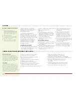
BindinG Procedure

1

  Make sure the transmitter and vehicle are both powered OFF.

2

  Install a bind plug in the receiver battery/bind port. You  

do not need to remove any of the other plugs to re-bind.

3

  With the bind plug installed, power ON the vehicle.  

The receiver LED will flash green.

4

  Move the steering wheel and throttle trigger to the failsafe 

positions and continue to hold those postions until the  

binding process is complete.

5

  Press the bind button on the transmitter while powering on 

the transmitter. The green LED on the transmitter will flash 

after 4 seconds when the transmitter is in bind mode.

6

  Release the bind button after the red LED on the  

transmitter flashes. Continue holding the failsafe positions 

until the receiver LED is solid. The green LED on the receiver 

will glow solid when the transmitter and receiver are bound.

7

  Disconnect the battery from the ESC. Remove the bind plug 

from the receiver. The receiver will keep the binding to the  

transmitter until another binding is done.

TransmiTTer and reCeiVer bindinG 

 / / / / / / / / / / / / / / /


/ / / / / / / / / / / / / / / / / / / / / / / / / / / / / / / / / / / / / / / / / / / / / / / / / / / / /

ConTrol TesT 

 / / / / / / / / / / / / / / /


/ / / / / / / / / / / / / / / / / / / / / / / / / / / / / / / / / / / / / / / / / / / / / / / / / / / / / / / / / / / / / / / / / / / / / / / / /

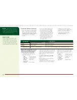
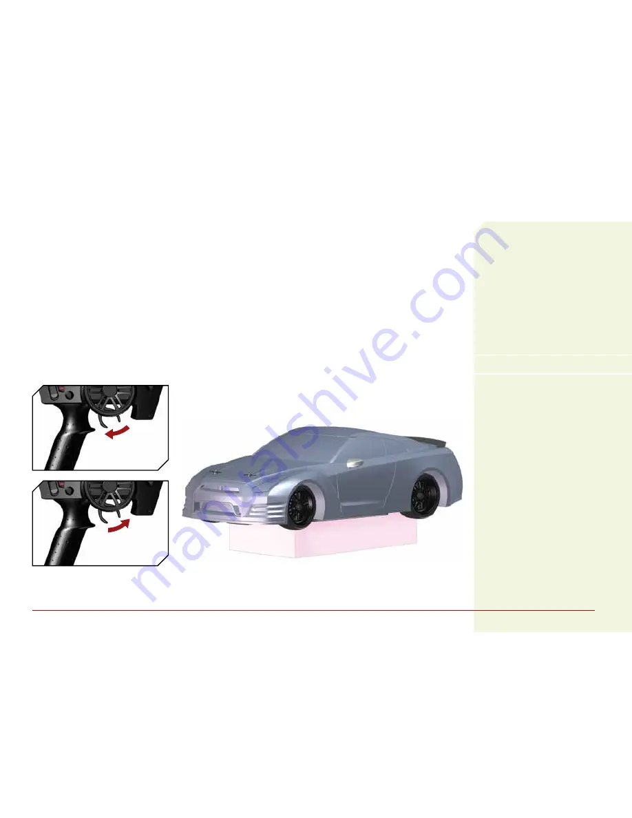
Perform a control test with the vehicle 

wheels off the ground. If the wheels 

rotate after the vehicle is powered  

ON, adjust the “TH. Trim” knob until 

they stop. To make the wheels move 

forward, pull the trigger. To reverse 

them, wait for the wheels to stop, 

then push the trigger. When moving 

forward, the wheels should maintain 

a straight line without any steering 

wheel input. If not, adjust the “ST. 

Trim” knob so the wheels maintain  

a straight line without having to  

turn the steering wheel.

Brake/reVerSe

forWard

Summary of Contents for 2012 Nissan GT-R V100-S

Page 1: ...owner s manual bedienungsanleitung manuel de l utilisateur manuale dell utente 2012 Nissan GT R V100 S...

Page 2: ...2...

Page 3: ...EN...

Page 4: ...manual to become familiar with the features of the product before operating Failure to operate the product correctly can result in damage to the product personal property and cause serious injury This...

Page 5: ...compressed air to dry the vehicle and help remove any water that may have gotten into small crevices or corners Spray the bearings drive train fasteners and other metal parts with WD 40 solvent or any...

Page 6: ...ing the competition in your dust just like the full size Table of Contents Quick Start Please read the entire manual to gain a full understanding of the V100 sedan fine tuning the setup and performing...

Page 7: ...A Ni MH AC Charger 4 AA Batteries for transmitter Components required tools Hobby grade knife Needle nose pliers Side cutting pliers Safety goggles Soldering iron Soft brush Use only Dynamite tools or...

Page 8: ...unattended exceed maximum charge rate charge with non approved batteries or charge batteries in the wrong mode Failure to comply may result in excessive heat fire and serious injury CAUTION If at any...

Page 9: ...itter Installing The Transmitter Batteries 1 Push in the battery cover a small amount to release the retaining tab then remove the cover 2 Install 4 AA batteries taking care to align the battery polar...

Page 10: ...n of the steering when the wheel is turned left or right 11 TH REV reverses the function of the speed control when pulled back or pushed forward For more information on the trans mitter go to www hori...

Page 11: ...sh after 4 seconds when the transmitter is in bind mode 6 Release the bind button after the red LED on the transmitter flashes Continue holding the failsafe positions until the receiver LED is solid T...

Page 12: ...before driving the vehicle again Remove the body of the vehicle to reduce cooling time run time Examine your vehicle on a regular basis Use a brush to remove dirt and dust Look for damage to the suspe...

Page 13: ...hen power on the ESC 3 Continue holding the throttle trigger at the maximum forward position until a beep sounds and both red and green LEDs flash then release the throttle to neutralposition 4 The ES...

Page 14: ...ith Smart Brake Green LED Forward Only Flashing with Brake Red Green LED Solid Crawler Mode NOTICE Crawler mode is for use on rocky surfaces only Do not use this mode with your vehicle on any other su...

Page 15: ...m Pinion Gear B 23 77 12 32 8 93 C 24 77 12 32 8 56 D 25 77 12 32 8 21 E 26 77 12 32 7 90 F 27 77 12 32 7 60 STD 77T Spur Gear with max Pinion Gear G 28 77 12 32 7 33 H 29 77 12 32 7 08 I 30 77 12 32...

Page 16: ...all the way Replace or repair servo Won t turn in one direction Servo gears damaged Replace servo Motor does not run Motor plugs loose Motor wire broken ESC damaged Plug in completely Repair or replac...

Page 17: ...the place of purchase Law These terms are governed by Illinois law without regard to conflict of law principals This warranty gives you specific legal rights and you may also have other rights which v...

Page 18: ...nt in the country of use and ownership If received a non compliant Product will not be serviced Further the sender will be responsible for arranging return shipment of the un serviced Product through...

Page 19: ...A11 2009 A1 2010 A12 2011 EN 55022 2010 AC 2011 EN 55024 2010 EN 61000 3 2 2006 A1 2009 A2 2009 EN 61000 3 3 2008 Signed for and on behalf of Horizon Hobby Inc Champaign IL USA Decmeber 9 2012 Compli...

Reviews: