background image

EN

DynamIte 12t esC 

 / / / / / / / / / / / / / / / / / / / / / / / / / / / / / / / / / / / / / / / / / / / / / / / / / / / / / / / / / / / / / / / / / / / / / / / / / / / / / / / / / / / / / /

SPecificationS

type 

Brushed

constant/Peak  

40A/180A

resistance 

0.002 Ohms

function 

Forward/Brake/Reverse;  

Forward/Brake

Vehicle type 

 1/12 on-road; 1/10 on- and off-road; 

1/10 rock crawler

operation 

Proportional forward, proportional 

reverse with braking delay

input Voltage 

2-cell Li-Po, 5-9 cell Ni-MH/Ni-Cd

Motor type 

540-/550-size closed endbell  

motors: 2S Li-Po down to 8T

Bec output 

5V/2A

overload Protection 

Thermal

dimensions 

1.40 in x 1.34 in x 0.71 in  

(35.6 x 34 x 18mm)

Weight 

1.41 oz (40 g) with wires

Battery connector 

EC3 connector

Motor connector 

3.5mm Tamiya style bullet

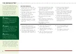
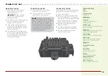
MountinG the eSc

1

   Mount the ESC in the location  

specified by your vehicle’s  

instruction manual.


Important:

 Ensure all wiring  

connections can be reached  

prior to mounting.

2

  The ESC can be mounted in vehicles 

with mounting posts using the  

removable mounting tabs.

3

  If the vehicle doesn’t have mount-

ing posts, remove the tabs and use 

double-sided foam tape to secure  

the ESC in position.

4

  The switch can be mounted to the 

side of the ESC with the slide mount. 

Or use double-sided foam tape to 

secure the switch in a convenient 

location in the vehicle.

connectinG the eSc

1

  Connect the RED (+) ESC wire  

to the RED (+) motor wire.

2

  Connect the BLACK (–) ESC wire  

to the BLACK (–) motor wire.

notICe:

 Always disconnect the 

battery from the ESC when you have 

finished operating your vehicle. The 

ESC’s switch only controls power 

to the receiver and servos. The ESC 

will continue to draw current when 

connected to the battery, resulting 

in possible damage to the battery 

through over-discharge.

caliBratinG the eSc

Ensure proper ESC function by calibrat-

ing the ESC to your transmitter inputs.

1

  Power OFF the ESC.

2

  Ensure your transmitter is powered 

ON, the throttle is not reversed, the 

throttle trim is neutral and the throttle 

travel range is at 100%. Disable any 

special functions such as ABS, etc.

3

  Keep the throttle at neutral and  

power ON the ESC.

4

  The ESC automatically calibrates  

the throttle range after 3 seconds.

5

  One long beep will sound when  

the ESC is ready to run.

Summary of Contents for Chevrolet Corvette 2014

Page 1: ...owner s manual bedienungsanleitung manuel de l utilisateur manuale dell utente 2014 Chevrolet COrvette...

Page 2: ...manual to become familiar with the features of the product before operating Failure to operate the product correctly can result in damage to the product personal property and cause serious injury This...

Page 3: ...and gently rinse the mud and dirt off with a garden hose Avoid rinsing the bearings and transmission NOTICE Never use a pressure washer to clean your vehicle Use an air compressor or a can of compress...

Page 4: ...oving in the correct direction 7 Drive your vehicle 8 Perform any necessary maintenance WARNING AGAINST COUNTERFEIT PRODUCTS Thank you for purchasing a genuine Spektrum product Always purchase from a...

Page 5: ...AC Charger 4 AA Batteries for transmitter Components required tools Hobby grade knife Needle nose pliers Side cutting pliers Safety goggles Soldering iron Soft brush Use only Dynamite tools or other...

Page 6: ...ge with non approved batteries or charge batteries in the wrong mode Failure to comply may result in excessive heat fire and serious injury CAUTION If at any time during the charging process the batte...

Page 7: ...itter Installing The Transmitter Batteries 1 Push in the battery cover a small amount to release the retaining tab then remove the cover 2 Install 4 AA batteries taking care to align the battery polar...

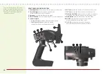
Page 8: ...ON OFF for the transmitter 5 Indicator Lights Solid green light indicates adequate battery power Flashing green light indicates the battery voltage is critically low Replace batteries 6 ST Trim adjust...

Page 9: ...ash after 4 seconds when the transmitter is in bind mode 6 Release the bind button after the red LED on the transmitter flashes Continue holding the failsafe positions until the receiver LED is solid...

Page 10: ...before driving the vehicle again Remove the body of the vehicle to reduce cooling time run time Examine your vehicle on a regular basis Use a brush to remove dirt and dust Look for damage to the suspe...

Page 11: ...d use double sided foam tape to secure the ESC in position 4 The switch can be mounted to the side of the ESC with the slide mount Or use double sided foam tape to secure the switch in a convenient lo...

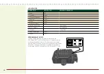
Page 12: ...y 1 Long Beep Battery Low Voltage Blinks Overheat Blinks Programming the ESC The ESC comes with two jumpers pre installed in the REV ON and BATT Ni MH configurations To disable reverse or change the b...

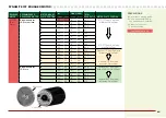
Page 13: ...m Pinion Gear B 23 77 12 32 8 93 C 24 77 12 32 8 56 D 25 77 12 32 8 21 E 26 77 12 32 7 90 F 27 77 12 32 7 60 STD 77T Spur Gear with max Pinion Gear G 28 77 12 32 7 33 H 29 77 12 32 7 08 I 30 77 12 32...

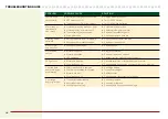
Page 14: ...all the way Replace or repair servo Won t turn in one direction Servo gears damaged Replace servo Motor does not run Motor plugs loose Motor wire broken ESC damaged Plug in completely Repair or replac...

Page 15: ...governed by Illinois law without regard to conflict of law principals This warranty gives you specific legal rights and you may also have other rights which vary from state to state Horizon reserves t...

Page 16: ...be responsible for arranging return shipment of the un serviced Product through a carrier of the sender s choice and at the sender s expense Horizon will hold non compliant Product for a period of 60...

Page 17: ...1 489 17 V2 1 1 2009 EN 60950 1 2006 A11 2009 A1 2010 A12 2011 EN 55022 2010 AC 2011 EN 55024 2010 EN 61000 3 2 2006 A1 2009 A2 2009 EN 61000 3 3 2008 Signed for and on behalf of Horizon Hobby LLC Cha...

Reviews: