background image

EN

DynamiTe fuze 540 4-pole 3300kV sensorless brushless moTor

PrecautionS


»

Never touch moving parts.


»

Never disassemble while the batteries are installed.


»

Always let parts cool before touching.

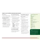
adjuStinG tHe SliPPer

Turn the 5mm adjustment nut clockwise (to the right) to reduce 

the slip or counterclockwise (to the left) to increase the slip.

cHanGinG tHe Pinion Gear/Gear ratio

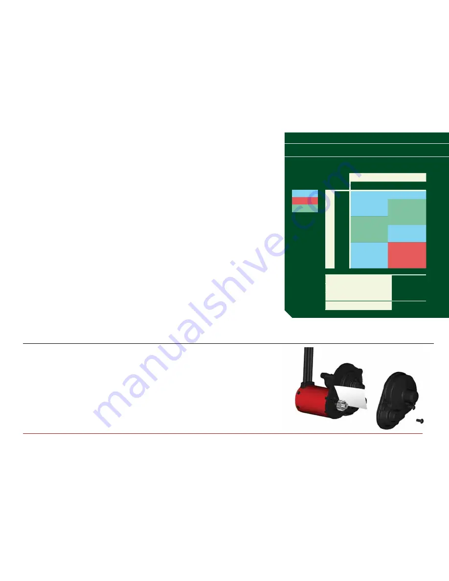
Your vehicle comes with the 20T pinion gear. To change to an-

other pinion gear (sold separately), follow the directions below.

1

  Unscrew the 3 screws holding the gear cover/motor mount 

in place.

2

  Remove the motor gear cover.

3

  Remove the pinion gear.

4

  Remove the screws holding the motor and move to the  

appropriate holes (marked with the number of teeth on  

the pinion) and reinstall the screws.

5

  Place the new pinion gear on the motor shaft.

6

  Reinstall the gear cover.

GearinG

Your vehicle has been equipped with the 

optimal gearing for the stock platform. It 

offers an ideal balance between speed, 

power and efficiency. Should you decide 

to customize your vehicle with optional 

batteries or motors, it may be necessary 

for you to change the pinion  or spur gear.
Installing a pinion gear with less teeth or 

a spur gear with more teeth will provide 

greater torque but will reduce top speed. 

Likewise, a pinion gear with more teeth or 

a spur gear with fewer teeth will reduce 

torque and increase top speed. Care 

should be taken when installing larger 

pinion gears as this can “overgear” the 

vehicle, resulting in overheating of the 

motor and ESC. When testing differ-

ent gearing options, pay close atten-

tion to the temperature of the motor 

and speed control to ensure you are 

operating within the temperature range 

of the components. The motor or ESC 

should never be so hot that it cannot be 

touched. If temperatures are too hot, 

a different gearing combination with a 

lower pinion gear and/or higher spur gear 

is suggested.

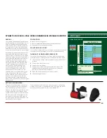
To set the gear mesh, screw the motor into the corresponding  

marked set of holes.  For example, with a 20T pinion, the motor  

screws must be screwed into the holes labeled “20”.

SettinG tHe Gear MeSH

The gear mesh has already been set at 

the factory, and setting it is only neces-

sary when changing motors or gears.
Proper gear mesh (how gear teeth meet) 

is important to the performance of the 

vehicle. When the gear mesh is too loose, 

the spur gear could be damaged by the 

pinion gear of the motor. If the mesh is 

too tight, speed could be limited and the 

motor and ESC will overheat.

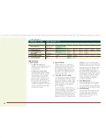
Gear CharT  

/ / / / / / / / / / / / / / / / / / / / / / / / / / / /

final driVe ratio

2S

3S

Pinion

16T

14.52

14.52

17T

13.66

13.66

18T

12.91

12.91

19T

12.23

12.23

20T

11.61

11.61

21T

11.06

11.06

22T

10.56

10.56

23T

10.10

10.10

24T

9.68

9.68

internal Gear ratio

2.67

SPur

87

Pinion

20

final driVe ratio

11.61

Marginal

thermo

oK

final driVe ratioS

eXaMPle

Summary of Contents for Halix RTR Monster Truck

Page 1: ...owner s manual bedienungsanleitung manuel de l utilisateur manuale dell utente h lix...

Page 2: ...2...

Page 3: ...EN...

Page 4: ...manual to become familiar with the features of the product before operating Failure to operate the product correctly can result in damage to the product personal property and cause serious injury This...

Page 5: ...and gently rinse the mud and dirt off with a garden hose Avoid rinsing the bearings and transmission NOTICE Never use a pressure washer to clean your vehicle Use an air compressor or a can of compress...

Page 6: ...n the vehicle Always power the transmitter ON before the vehicle and power it OFF after the vehicle has been powered OFF 5 Check the steering and throttle control directions Verify that the servos are...

Page 7: ...dering iron Use only Dynamite tools or other high quality tools Use of inexpensive tools can cause damage to the small screws and parts used on this type of model 1 10 Scale H lix RTR Monster Truck Sp...

Page 8: ...en the transmitter is bound to a DSMR receiver When the transmitter is bound to a DSM DSM2 or DSM Marine receiver the ST RATE knob controls the steering dual rate 1 Steering Wheel controls direction l...

Page 9: ...nsmitter and receiver are linked when the orange LED is solid 7 Pull the transmitter trigger to Full Throttle 8 Push the transmitter trigger to Full Brake then return the trigger to center 9 Turn the...

Page 10: ...and dust Look for damage to the suspension arms and other molded parts Re glue the tires to the wheels if necessary Clean and oil all wheel bearings Use suitable tools to tighten fasteners Make sure...

Page 11: ...t the ESC for your driving conditions ESC Programming Procedure Programming is accomplished using the SET button on the ON OFF switch Programming the ESC 1 Connect a fully charged battery to the ESC 2...

Page 12: ...Ni MH batteries if the voltage battery pack is higher than 9 0V it will be treated as a 3 cell Li Po battery pack if it is lower than 9 0V it will be treated as a 2 cell Li Po battery pack Example for...

Page 13: ...r with more teeth or a spur gear with fewer teeth will reduce torque and increase top speed Care should be taken when installing larger pinion gears as this can overgear the vehicle resulting in overh...

Page 14: ...attery pack to the ESC 4 Power on the ESC The orange LED flashes indicating the receiver is in bind mode 5 Center the ST TRIM and TH TRIM dials on the transmitter 6 Press and hold the BIND button whil...

Page 15: ...Servo gears damaged Replace servo Motor does not run Motor plugs loose Motor wire broken ESC damaged Plug in completely Repair or replace as needed Contact Horizon Hobby Product Support ESC gets hot M...

Page 16: ...ity If you as the purchaser or user are not prepared to accept the liability associated with the use of the Product purchaser is advised to return the Product immediately in new and unused condition t...

Page 17: ...om content _service center_render service center ATTENTION Horizon service is limited to Product compliant in the country of use and ownership If received a non compliant Product will not be ser viced...

Page 18: ...device Declaration of Conformity in accordance with ISO IEC 17050 1 No HH2013092903 Product s VTR H lix 4WD Monster Truck Spektrum DX2E transmitter and SRS4200WP receiver included Item Number s VTR03...

Reviews: