background image


USER MANUAL


Vauconsant SA, all rights reserved A635xx -rev0-ENG, 22/10/2010                                                    - 11 - 


i.


Enter the Pr2 programming mode 


To access settings present in "Pr2" (accessible to technicians), please contact 

, who will give you 

the secret code to access these settings. 


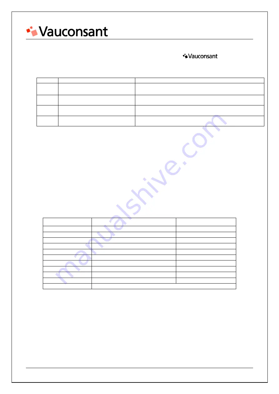
4.


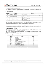
Alarm signals 


Message 

Cause 

Outputs 

"P1" 

Atmospheric probe fault 

ON alarm output 
Compressor output depending on "COn" and "COF" settings 

"HA" 

High temperature alarm 

ON alarm output 
Other outputs unchanged 

"LA" 

Low temperature alarm 

ON alarm output 
Other outputs unchanged 

"EE" 

Memory breakdown or fault 

ON alarm output 
Other outputs unchanged 


The  alarm  message  is  displayed  until  the  alarm  condition  is  re-established.  All  alarm  messages  are  displayed 
alternately  with  the  atmospheric  temperature  except  for  "P1"  which  flashes.  To  reset  the  "EE"  alarm  and  start 
normal operation again, press on any key. The "

rSt

" message will be displayed for 3 seconds.


a.


The EE alarm 


The regulator includes an internal memory checking system. The "

EE

" alarm flashes when an internal memory fault 

has been detected. In this case, the alarm output is activated.


b.


Reestablishment of alarms 


"

P1

" probe alarms (probe defect), "

P2

": they stop automatically 10 seconds after the probe has resumed normal 

operation. Check the connections before putting back the probe.


"

HA

"  and  "

LA

"  temperature  alarms:  they  stop  automatically  when  the  regulator's  temperature  returns  to  normal 

values or when defrosting starts.


5.


Settings programmed in the factory 


Setting 

Name 

Value 

Set 

 Set point 

-8 

Hy 

 Differential 

AC 

 Anti-short cycle time 

rES 

 Resolution 

dE 

IdF 

 Interval between defrosting cycles 

MdF 

 (Maximum) defrosting time 

ALU 

 High temperature alarm 

ALL 

 Minimum temperature alarm 

ot 

 Atmospheric probe calibration 

Adr 

 Serial address (not used) 

P2r 

 Access to the list of protected settings (read only) 


Summary of Contents for A63513

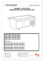
Page 1: ...EX XI IG GE EN NC CE E S ST TA AT TI IC C C CO OL LD D R RE EF FR RI IG GE ER RA AT TI IO ON N U UN NI IT T O ON N S ST TO OR RA AG GE E U UN NI IT T A63513 3GN 1385 x 820 x 900 mm A63515 4GN 1580 x 820 x 900 mm A63517 4GN 1580 x 820 x 900 mm A63519 5GN 1930 x 820 x 900 mm A63524 6GN 2280 x 820 x 900 mm A63525 7GN 2605 x 820 x 900 mm Child version E63513PI1D 3GN 1385 x 820 x 750 430mm E63515PI1D 4...

Page 2: ...ENG 22 10 2010 2 Manual to be read and kept Contents Introduction 3 Installation 4 Commissioning Use 6 Cleaning 7 Diagnostic 8 Maintenance 9 Thermostat instructions settings 10 Electric and refrigeration diagrams 13 Spare parts Technical support 15 Warranty 17 ...

Page 3: ...mperature lower than 8 C at core in a room temperature of 25 C for a maximum 60 minutes Ventilated refrigeration is designed to work around the clock The temperature of the food provided should be between 0 C and 3 C These units comply with applicable EC norms and should be installed and used following the instructions in this manual to ensure good performance and to be covered by the warranty ...

Page 4: ...the black non slip adhesive patches in the specified markings on the part of the bracket in contact with the breath shield 3 Install the glass the non domed end should be positioned 120 km from the edge of the beam In the case of the salad bar option centre the glass 4 Tighten the upper brackets Overhang adjustment The unit s overhangs should be positioned as shown below The unit should be level U...

Page 5: ... reserved A635xx rev0 ENG 22 10 2010 5 Assembly dismantling of facing Option with condensation generator not supplied The connection should be done by a professional refrigerating technician Mounting with spanner rack supply Step 1 Step 2 ...

Page 6: ... tests When the temperature required is reached the generator stops automatically Press the thermostat button to stop regulation of the unit Storage unit The ventilated storage unit starts natural defrosting every 6 hours for 30 minutes Lighting option Press the thermostat button to switch lighting on and off Setting of the thermostat See section User instructions for the XW40L thermostat Automati...

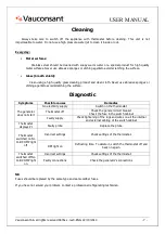
Page 7: ...ptoms Possible causes Remedies No electricity supply Switch on the thermostat Thermostat off Check the general circuit breaker Check the fuse in the switch cabinet The generator does not start Faulty supply Check tightening of the lugs and wires on all the internal and external cabling of the switch cabinet Thermostat displays P1 Faulty probe Replace the probe Incorrect settings Check settings of ...

Page 8: ...W A63515 E63515PI1D E63515PI1G 4GN 396 W 400 W A63517 4GN 665 W 100 W A63519 E63519PI1D E63519PI1G 5GN 665 W 600 W A63524 6GN 800 W 100 W A63525 7GN 800 W 750 W Evaporation well option 300 W Procedure Every 4 months check that the condenser is not clogged and clean it properly Every year check that the condenser s ventilator works properly The installer should check electric connections when commi...

Page 9: ...rd F F F C V To display and modify the set point In the programming mode used to select a setting or confirm an operation By pressing this key for 3 seconds when the maximum or minimum temperature is displayed it will be erased To display the maximum temperature recorded In programming mode is used to browse through the list of settings or increase the displayed value By pressing this key for 3 se...

Page 10: ... Display the maximum temperature Press and release this key The Hi message is displayed followed by the maximum temperature recorded By pressing this key again or waiting 5 seconds the normal display returns e Reset minimum and maximum temperatures To reset the recorded temperature when the maximum or minimum temperature is displayed press on the SET key until the rST code starts to flash N B Afte...

Page 11: ... normal operation again press on any key The rSt message will be displayed for 3 seconds a The EE alarm The regulator includes an internal memory checking system The EE alarm flashes when an internal memory fault has been detected In this case the alarm output is activated b Reestablishment of alarms P1 probe alarms probe defect P2 they stop automatically 10 seconds after the probe has resumed nor...

Page 12: ...USER MANUAL Vauconsant SA all rights reserved A635xx rev0 ENG 22 10 2010 12 Generator option supplied Electric diagram Refrigeration diagram ...

Page 13: ...tion diagram Caption B Ballast Rd Defrosting heating element C Compressor S Coil Ca Capillary Sf Starter Cd Condenser St Temperature probe D Reducing valve T XW40L thermostat Dh Dehydrator Tf Fluorescent tube Kd Defrosting contactor Va Schraeder 1 4 connection Q Fuse holder Vc Condenser ventilator Rb Evaporation well heating element ...

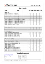
Page 14: ...273 Dixell XW40L thermostat X X X X X Compressor generator 12 2408 Storage unit transversal evaporator X X X X X 12 2506 CHILD Storage unit transversal evaporator X X X X X 12 2752 AEZ 3430 ZH condensation generator X X 12 2755 AEZ 3450 ZH condensation generator X 12 2783 CAE 9460 ZMH condensation generator X Fluorescent tube lighting 06 4780 590mm 18W power fluorescent tube X 06 4784 970mm 36W po...

Page 15: ...d by defects or poor maintenance of equipment or damage caused by knocks or improper use Any warranty also excludes incidents caused by fortuitous events or force majeure unidentified causes or causes by the buyer s actions of any form whatsoever improper location faults linked to use operation maintenance not in accordance with this manual unqualified staff etc modification of the equipment repai...

Reviews: