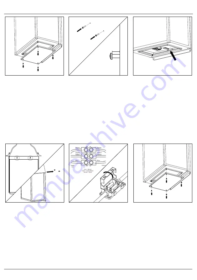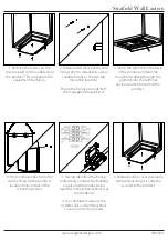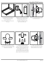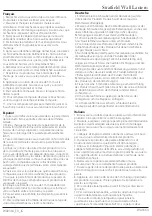
6. Reattached the cover previously
removed ensuring it is correctly
secured to the product.
5. Having identified the house-
hold wiring, connect the building
supply and the product wires
together in the terminal block/s as
shown above.
Once complete make sure the
flexible seals and terminal block
cover are correctly secured.
(
4. Position the product onto the
wall by lining up the product's
location holes to that of the
mounting screws.
3. Pierce the grommit in the back
of the product and feed the
household cabling through the
grommit into the terminal
enclosure at the bottom of the
product.
2. Measure and mark out the wall
fixings prior to installation. Screw
suitable fixings to the two top
mounting locations.
Ensure the fixings protrude from
the wall approximately 8mm
8mm
1. Remove the screws on the
cover located on the underside of
the product. This will expose the
sealed terminal block.
After choosing a suitable location that meets all the requirements of
the safety information install the unit following the steps overleaf.
- Carefully unpack all parts and check for damage or missing parts
before commencing installation.
- Installation of this product must be carried out by a qualified
electrician.
- Disconnect the electrical supply before installation. Switch off the
electricity at the fuse box by removing the relevant fuse or switching
off the circuit breaker before proceeding with the installation.
- Install should be carried out in accordance with the wiring regulations
and building codes applicable to the country of installation.
- Before making any fixing hole(s), check that there are no obstructions
hidden beneath the mounting surface such as pipes or cables.
- Ensure that the support for the light is of sufficient structural strength and that any fixing screws do not
interfere with the connecting cables.
- The unit can get very hot during use. Switch the product off and allow to cool before handling or changing
bulbs. .
- Ensure adequate ventilation space is allowed between the unit and any object above, in front or to either
side of the unit. Suggested minimum space is 0.5m above and 0.5m on all sides.
- To prevent tarnishing, it is advisable to wear gloves at all times when handling the product.
- Mains connector must be a lever slicing connector; with a minimum of 3 terminals; rated to 240v 16A
(minimum); conforming to IEC 60998-2-1 or IEC 60998-2-7
www.vaughandesigns.com
Stratfield Wall Lantern
Stratfield Wall Lantern
WA0364


