Hardware Installation
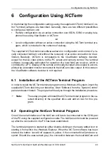
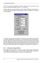
NetCam1S, NetCam6, NetCamPlus Manual, © VCS GmbH
30
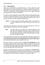
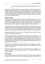
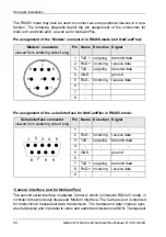
The RS485 mode may also be used to connect several peripheral devices in a bus-
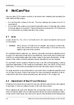
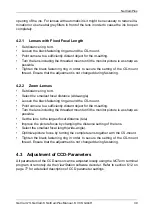
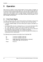
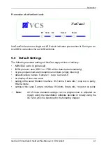
fashion. The following diagrams depict the pin assignment of the connectors for
NetCam1 and NetCam6, as well as for NetCamPlus.
Pin assignment of the ’Modem’ connector in RS485-mode (not NetCamPlus):
Pin assignment of the serial interface for NetCamPlus in RS485-mode:
‘Camera’-Interface (not for NetCamPlus)
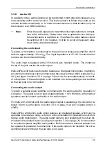
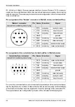
The second serial interface is labelled ‘Camera’, which is limited to RS232C mode, in
contrast to the previously discussed ’Modem’ interface. The ’Camera’-port is intended
for bidirectional transparent data transmission. The transparent data channel oper-
ates full-duplex and in parallel to video and audio transmission via ISDN. Transparent
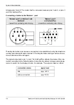
‘Modem’ connector
viewed from soldering side of plug
Pin Name Direction Signal
1
TxD + outgoing
transmit data
2
RxD + incoming
receive data
3
TxD -
outgoing
transmit data
4
GND
ground
5
RxD -
incoming
receive data
6
-
7
-
8
-
Serial interface connector
viewed from soldering side of plug
Pin Name Direction Signal
1
-
-
-
2
RxD -
incoming
receive data
3
TxD -
outgoing
transmit data
4
-
-
-
5
GND
ground
6
-
-
-
7
TxD + outgoing
transmit data
8
RxD + incoming
receive data
9
-
-
-
3
6
8
5
7
1
2
4
1
2
3
4
5
6
7
8
9
Summary of Contents for NetCam1
Page 1: ...NetCam1 NetCam6 NetCamPlus Manual VCS Video Communication Systems GmbH...
Page 6: ...NetCam1S NetCam6 NetCamPlus Manual VCS GmbH 6...
Page 42: ...NetCam1S NetCam6 NetCamPlus Handbuch VCS GmbH 42...
Page 80: ...Configuration Using NCTerm NetCam1S NetCam6 NetCamPlus Manual VCS GmbH 80...
Page 90: ...Appendix NetCam1S NetCam6 NetCamPlus Manual VCS GmbH 90...

