Hardware Installation
NetCam1S, NetCam6, NetCamPlus Manual, © VCS GmbH
36
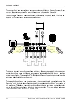
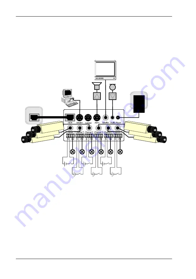
The shown light bulb symbolizes remote control possibilities of the built-in relay. Con-
nection of external sensors for alarm triggering is indicated by the switch.
Connecting 6 cameras, a local monitor, audio I/O, 6 external alarm sensors as
well as 6 actuators to a NetCam6 sending unit:
The same remarks as for the previous NetCam1 diagram also apply to the diagram
above. Also here many peripheral components are depicted which are not required
for each application. The depicted PC, if only used for configuration purposes, can be
removed after installation and set-up.
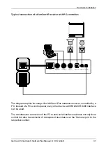
The depicted installation can be extended by transparent data transmission via the
’Camera’ port. Another alarm input and switching output at the ’Alarm’ connector is
still available. This alarm channel can be configured as a so-called master-alarm in-
put, which will arm or disarm all other alarm channels. Typically, a key-operated
switch is connected to the master-alarm input.
Summary of Contents for NetCam1
Page 1: ...NetCam1 NetCam6 NetCamPlus Manual VCS Video Communication Systems GmbH...
Page 6: ...NetCam1S NetCam6 NetCamPlus Manual VCS GmbH 6...
Page 42: ...NetCam1S NetCam6 NetCamPlus Handbuch VCS GmbH 42...
Page 80: ...Configuration Using NCTerm NetCam1S NetCam6 NetCamPlus Manual VCS GmbH 80...
Page 90: ...Appendix NetCam1S NetCam6 NetCamPlus Manual VCS GmbH 90...

