background image

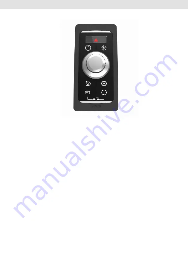
AcquaLink® Nav Control 

The AcquaLink

®

 Nav Control unit enables skippers to assume control of

AcquaLink

®

 TFTs in any situation.

Screens can be switched and menus and input variables navigated by using 

the push / turn knob and six other push buttons. A Nav Control unit can 

assume control of any display connected to the same VDO Bus with just the 

push of a button. Even multiple units can be connected to the same Bus 

without conflicts.

In the Box

 -Nav Control

 -Bezel

 -Template

 -Installation Instruction

6                                                       

Summary of Contents for AcquaLink

Page 1: ...Nav Control V1 1 08 16 Installation Instruction ...

Page 2: ...2 ...

Page 3: ...Content Installation 4 Safety Instructions for Maintenance 5 AcquaLink Nav Control 6 In the Box 6 VDO Bus 7 Hardware Specification 9 Pinout 9 Specifications 10 Accessory 10 3 ...

Page 4: ... Wearing of metallic or conductive jewellery such as necklaces bracelets rings etc is not allowed when working on the electrical installation on board Please note that with disconnection of the battery all volatile electronic memories lose their input values and must be reprogrammed VDO Nav Control Installation This product has been developed manufactured and tested in accordance with the requirem...

Page 5: ...O approved cables If you don t use standard cables the wires used should be adequately insulated or should have sufficient electrical strength and the contact point should be protected against electrical shock hazard The electrical conducting components of the connected consuming devices should also be protected against direct contact through suitable measures Installation of bare metallic wires a...

Page 6: ...d and menus and input variables navigated by using the push turn knob and six other push buttons A Nav Control unit can assume control of any display connected to the same VDO Bus with just the push of a button Even multiple units can be connected to the same Bus without conflicts In the Box Nav Control Bezel Template Installation Instruction 6 ...

Page 7: ...sy installation in all areas of the vessel Every 110mm gauge 4 3 TFT and Nav Control features two equal VDO Bus connectors in the rear The units are daisy chained together Segments have to be terminated with a VDO Terminator included in the Nav Box box If you haven t connected an instrument or Nav Control to a Nav Box port connect the terminator directly to the not used Nav Box VDO port If you hav...

Page 8: ...of the VDO Bus is calculated as follows Ohm s Law E voltage drop I circuit current x R wire resistance R 2 2x Cable Length m x Power Pair Resistance 100 L Total length of VDO Bus cables in one segment I LEN Load Equivalency Number x 0 050 amps E 0 05 x LEN x L x 0 057 The voltage drop for each VDO Bus Segment shouldn t be higher than 3V Note VDO BUS has 2x AWG 22 Power Ground cables so there is a ...

Page 9: ...Hardware Specification Front View with bezel Front View without Bezel Side view Rear view Pinout 9 ...

Page 10: ...nge 8 28 VDC Protection Class IP 67 According to IEC 60529 2001 in nominal position EMC DIN EN 61000 6 2 2006 IEC 60945 2002 Approval EC Accessory A2C Number Description A2C96244600 VDO Bus Cable 0 5m A2C96244900 VDO Bus to NMEA 2000 Adapter A2C38805700 VDO Bus Cable 2m A2C96245000 VDO Bus Cable 5m A2C96245100 VDO Bus Cable 10m A2C99793900 Termination Resistor VDO Bus A2C38805500 Gender Changer VD...

Page 11: ...11 ...

Page 12: ...ich may change as a result of further development of the products This information is merely a technical description of the product It is not meant or intended to be a special guarantee for a particular quality or particular durability An obligation to provide the respective characteristics shall only exist if expressly agreed in the terms of contract We reserve the right to make changes in availa...

Reviews: