background image

1-   BARRIER

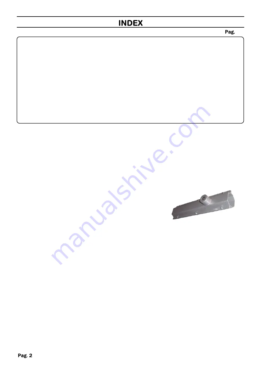
1- BAR SUPPORT

PACKING CONTENTS .......................................................................

2

DIMENSIONS ......................................................................................

3

CONSIDERATIONS FOR INSTALLATION..........................................

3

INSTALLATION....................................................................................

4-5-6

SAFETY PRECAUTIONS ...................................................................

7

PACKING CONTENTS

Summary of Contents for BERTA M

Page 1: ...hly read this manual that is an integral part of the pack The CE mark conforms to European directive EEC 89 336 92 31 93 68 D L 04 12 1992 N 476 Our products if installed by qualified personnel capable to evaluate risks comply with norms UNI EN 12453 EN 12445 ...

Page 2: ...1 BARRIER 1 BAR SUPPORT PACKING CONTENTS 2 DIMENSIONS 3 CONSIDERATIONS FOR INSTALLATION 3 INSTALLATION 4 5 6 SAFETY PRECAUTIONS 7 PACKING CONTENTS ...

Page 3: ... Ÿ The installation and testing operations must be performed by qualified personnel in order to guarantee the proper and safe operation of the automatic gate Ÿ The company declines any responsibility for damage caused by incorrect installations due to incompetence and or negligence ...

Page 4: ...t the floor plate Nuts Brackets Cable conduit hole Base plate Place the barrier on the floor plate and fasten it with the self locking M12 nuts supplied Fixing holes INSTALLATION WITHOUT BASE PLATE Place the barrier and block it through the four holes present internally on the basis SHAFT SUPPORT Insert the bar support on the shaft and fasten it with screws Insert the bar in the support and tighte...

Page 5: ...A to B of the output shaft Ÿ Reinsert the boom support Ÿ Reverse the position of the locking release knob positioned on the trapezoid inside the barrier A A B B Key Drive shaft front view DX SX Standard position SX Position DX Lock release knob To change the direction of opening from the left standard to the right proceed as follows OPENING DIRECTION Key ...

Page 6: ...Ÿ Close the cover CLOSING Lock release knob Lowered boom Raised boom Ÿ Acting on the lower tie nut put the spring in tension until the rod is balanced at 45 and the trapezoidal bracket will remain horizontal to the ground Ÿ The trapezoidal bracket has four holes which regulate the force of the spring according to the length of the bar The force of the spring is reduced the more it is placed intern...

Page 7: ... Read the instructions and enclosed documentation carefully The product must be used for the express purpose for which it was designed Any other use is considered improper and therefore hazardous In addition the information given in this document and in the enclosed documentation may be subject to modifications without prior notice It is given as an indication only for product application The comp...

Page 8: ...poltore PE ITALY Tel 39 085 4971946 FAX 39 085 4973849 www vdsautomation com info vdsautomation it The data and images are for guidance only VDS reserves the right to change at any time characteristics of the products described in its sole discretion without notice ...

Reviews: