background image

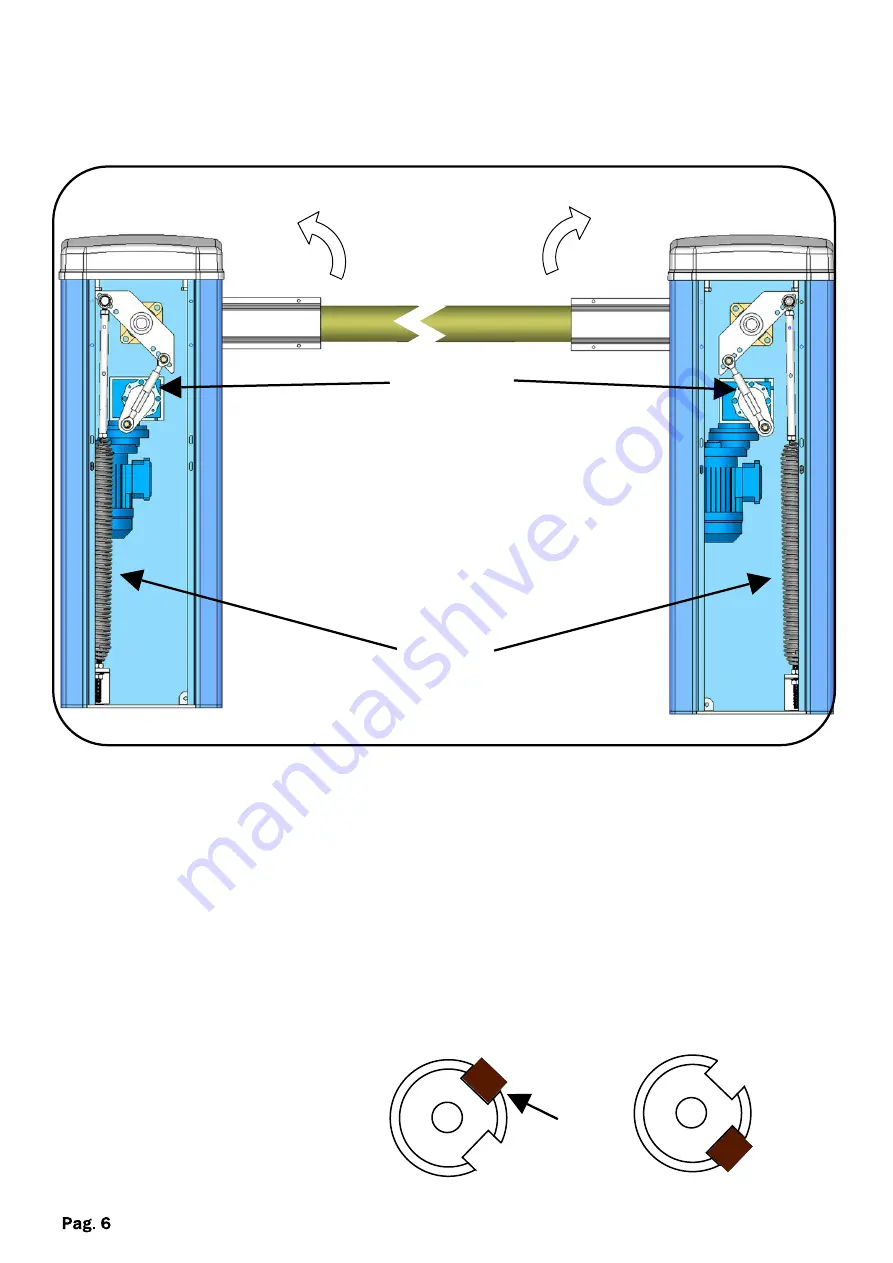
OPENING DIRECTION

To change the opening direction of the automation from the left (standard) to the
right proceed as follows:

SX

DX

- Discharge the spring tension

- Unhook the spring

- Unhook the arm

- Reverse the position of the spring with the arm

- Hook again and tighten everything

- Invert the position of the key from position

A

 to

B

of the output shaft.

- Reinsert the rod holder

A

A

B

B

key

Front view

transmission shaft

Sprin

arm

Summary of Contents for ITALO

Page 1: ...talling thoroughly read this manual that is an integral part of the pack The CE mark conforms to European directive EEC 89 336 92 31 93 68 D L 04 12 1992 N 476 Our products if installed by qualified personnel capable to evaluate risks comply with norms UNI EN 12453 EN 12445 ...

Page 2: ...S 12 Pag PACKING CONTENTS 1 BARRIER 1 BAR SUPPORT TECHNICAL DATA 230V Maximum length of bar 3 mt Motors power supply 230Vac Motor power 250 W Motor RPM 1400 Condenser 16 µF Mechanical unlock for emergency manoeuvre Mechanical Working temperature 20 C 55 C Weight 45Kg Protection rating IP 44 Limit switch Electromechanical Opening time 3 sec ...

Page 3: ...Ÿ The installation and testing operations must be performed by qualified personnel in order to guarantee the proper and safe operation of the automatic gate Ÿ The company declines any responsibility for damage caused by incorrect installations due to incompetence and or negligence ...

Page 4: ...or plate INSTALLATION Set up an electrical multi duct conduit in the middle of the foundation of the barrier corresponding to the central hole corrugated diameter 25 50mm Place the barrier on the floor plate and fasten it with the self locking M12 nuts supplied Brackets Base plate Cable conduit hole INSTALLATION WITHOUT BASE PLATE Place the barrier and block it through the four holes present inter...

Page 5: ...er the motor until reaching the desired opening Note When you open the cover the automation blocks MANUAL OPENING SHAFT SUPPORT Insert the bar support on the shaft and fasten it with screws Insert the bar in the support and tighten the screws Screw Shaft Screw Key Bar support ...

Page 6: ...ed as follows SX DX Discharge the spring tension Unhook the spring Unhook the arm Reverse the position of the spring with the arm Hook again and tighten everything Invert the position of the key from position A to B of the output shaft Reinsert the rod holder A A B B key Front view transmission shaft Sprin arm ...

Page 7: ...switches Adjustment screw for the mechanical limit switches LIMIT SWITCHES REGULATIONS It s possible to adjust the limit switches position both the mechanical placed inside the barrier and electrical ones easily accessible as they are placed under the superior cover N B When one of the mechanical end stroke switches is repositioned it is necessary to relocate the electronically controlled one acco...

Page 8: ...motors is insufficient Modify the value with the FORCE trimmer on the control unit N B If the problem persists contact your Retailer or the nearest Service Centre TROUBLESHOOTING All products are guaranteed for 2 years as per the date on the invoice or on the receipt The warranty also does not include failures or damages caused by faults of the electrical system and or carelessness negligence or i...

Page 9: ...NOTE ...

Page 10: ...NOTE ...

Page 11: ...NOTE ...

Page 12: ...d by electromagnetic fields The presence of inflammable gases or fumes is a grave danger to safety Set up a safety device for overvoltage a disconnecting and or differential switch suitable for the product and conforming to current standards The manufacturer declines any and all responsibility for product integrity safety and operation in the event incompatible devices and or components are instal...

Reviews: