
LVP605 User’s Manual
---------------------------------------------------------------------------------------------------
LED VIDEO PROCESSOR
9
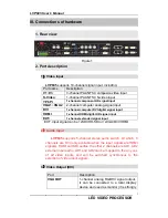
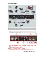
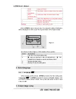
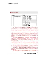
currently selected such as “input=HDMI” will appear in the first line
of LCD, while the status of current input signals will appear in the
second line of LCD. If there are no valid signals entered, the
message “no valid signal input” will appear in LCD, and the
corresponding indicator will blink and dark screen appear; if the
signal is valid, the format of input signals such as “ 1080p_60Hz ”
will appear in LCD.
2) VGA input auto adjustment (Auto)
When the current VGA input source of
LVP605
is a valid signal,
press this button,
LVP605
will automatically adjust the sampling
parameters of the VGA signals, so as to make VGA picture clean
and complete.
In general, this operation is made only when new VGA signal
source is to be connected in. Sometimes user need repetitively do
such adjustment till VGA picture looks clean, complete and stable.
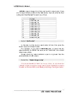
3) Information display (Info)
Press this button to view current settings and information of
LVP605
, it consists of 25 items. If you press “
Info
” again before
LVP605
exit information display,
LVP605
will continue to display
the next item of information.
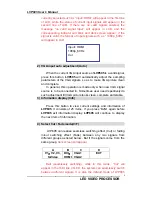
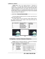
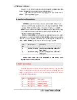
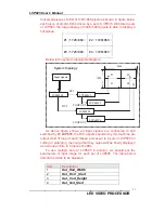
4) Select Cut / Fade mode(C/F)
LVP605 can realize seamless switching effect (Cut) or fading
in/out switching effect (Fade) between any two signals from
different groups as listed below.. But if the signals come from the
same group,
dark screen will appear.
A B
C
D
V1
,
V2, V3,
S-Video
DVI
,
HDMI
VGA1
VGA2
EXT
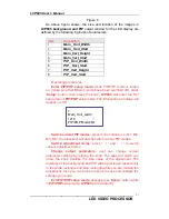
Cut
(seamlessly switching): while in this mode, “Cut” will
appear in the third line of LCD, the system can seamlessly switch
between different signals. It is also the default mode of LVP605
Input= HDMI
1080p_60Hz
Cut


