CWW / CWK / CFW / CFK
3
WATER CONNECTING
When connecting a heater/cooler to the water system, the
following things should be considered:
1.
The heater / cooler must be connected according to the
applicable regulations.
2. The connecting pipes from the heat exchanger must
under no circumstances be subjected to twisting or
bending stresses when assembling the pipe connectors
etc. Use suitable tools to counteract the twisting/bending
moments during assembly.
3. Ensure that forces due to expansion in the system and
the inrinsic weight of the piping system itself do not put
loads on to the heat exchanger.
4. The water inlet should normally be connected to the
lowest pipe connector in order to facilitate venting of the
heat exchanger. A venting valve should normally be
installed near the heat exchanger or at the highest point
in the system.
5. The heater/cooler must be connected in such a way that
the system is easy to empty in the event of repair work,
a longer operational stop, or when there is a risk of
freezing, etc.
6. Immediately after the system has been filled with water,
the duct heater and its connections must be checked for
water leaks. Leaks can cause water damage.
Operational data:
Max. operating temperature: 150°C
Max. operating pressure:
1,0 MPa (10 bar)
WARNING!!
If the water in the heat exchanger freezes, then it can burst,
if this is the case water may leak from the system and cause
water damage. Therefore, when there is a risk of freezing the
heater/cooler must be protected by a freezing sensor which
shuts down the system fans, shuts any outside air valves, opens
the water valve to increase the water circulation through the
heat exchanger, and activates the alarm circuit (if there is one).
CLEANING
The heat exchanger must be cleaned regularly in order to
retain the best performance from the heater/cooler. The
cleaning interval depends entirely on the cleanliness of
the air and how the filter and remainder of the system are
maintained.
The heat exchanger is readily accessible for cleaning when
the cover on the heater/cooler is removed. First, the air entry
side of the heat exchanger is cleaned with a brush and then
the whole heat exchanger can be cleaned with compressed
air, water or steam. The dirt is blown or washed away in a
direction away from the exit side towards the entry side.
Cleaning is facilitated by using a mild detergent (check first
that the detergent does not have a detrimental effect on
copper and aluminium).
Be careful not to damage the thin fins on the heat exchanger.
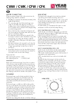
CWK
Drain
G 1/2
MOUNTING
The heater/cooler is designed to be inserted into standard
spiral ducting and is fixed to the ducting with screws.
The heater/cooler should not be fitted too close to a fan outlet
or a bend in the ducting because then there is a risk that the
air flow through the heat exchanger is uneven which can
result in lower efficiency.
An effective filter is recommended in the system to reduce
maintenance work. See under the heading Cleaning.
DUCT HEATER MODEL CWW / CFW
The duct heater can be fitted in a horizontal or a vertical duct
with optional direction of airflow. CWW/CFW duct heating
for hot water in round ventilation ducts.
CFW is insulated with 50 mm rock wool in a double-shell
housing. To facilitate venting of the heat exchanger, the unit
should be fitted with the longitudinal tubes horizontal. The
heater is normally fitted after the fan. However it can be fitted
before the fan, but then a check must be made that the fan
motor and other components are approved for the elevated
temperature after the heater.
DUCT COOLER MODEL CWK / CFK
The duct cooler must be fitted in a horizontal duct and the
airflow must be in the direction of the arrow. The CWK/
CFK must be insulated externally to prevent the formation of
condensation on its outside surfaces.
CFW is insulated with 50 mm rock wool in a double-shell
housing.
Normally, the ducts that transport cold air must also be
insulated to prevent condensation. A drain pipe is required
to drain off any condensed water. To prevent unnecessary
condensed water remaining in the duct cooler, it must be
tilted at an angle of 10-15 degrees to the horizontal in
the direction of the drain. See the picture below. Drain
connection is G 1/2. The duct cooler must be connected to
the drain in such a way that the connection is protected from
pulling, pressing or twisting. Otherwise there is a risk of water
leakage.
GB
/
CFK
Summary of Contents for CWW
Page 9: ...CWW CWK CFW CFK 9...


