24
GETTING TO KNOW YOUR MTC-4015
©Vecow MTC-4015 User Manual
The LCD inverter is connected to J2 via a JST 7-pin, 2.5mm connector providing
+5V/ +12V power to LCD display. The pin assignments are listed in the following
table:
Pin No.
Definition
Pin No.
Definition
1
+5V
5
GND
2
+12V
6
GND
3
+12V
7
LBKLT_EN
4
LBKLT_CTL
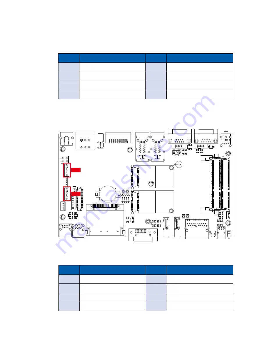
2.4.5 CN17, CN19 : SATA III Connector
There are 2 onboard high performance Serial ATA III (SATA III) on MTC-4015.
It supports higher storage capacity with less cabling effort and smaller required
space. The pin assignments of CN17 and CN19 are listed in the following table:
Pin No.
Definition
Pin No.
Definition
1
GND
5
RXN
2
TXP
6
RXP
3
TXN
7
GND
4
GND
CN17
CN19


