Page 2
"WHHR125DC- AERA" - WHOLE HOUSE HEAT RECOVERY UNIT
INSTALLATION AND OPERATING & MAINTENANCE INSTRUCTIONS
Safety Notice
It is important to read this Instruction Manual carefully before installing or using the product. Following
these instructions will ensure that your ventilation system is installed, commissioned and used properly and
continues to operate effectively. Vectaire will not be held responsible and will not accept liability for any dam-
age caused to persons or property through failure to follow the guidance provided in this manual. It should
always be available with the product for easy reference.
WHHR125DC - Aera:
5"/125mm spigot, for dwellings up to 150m
2
, max capacity 280m
3
/hr
General Information
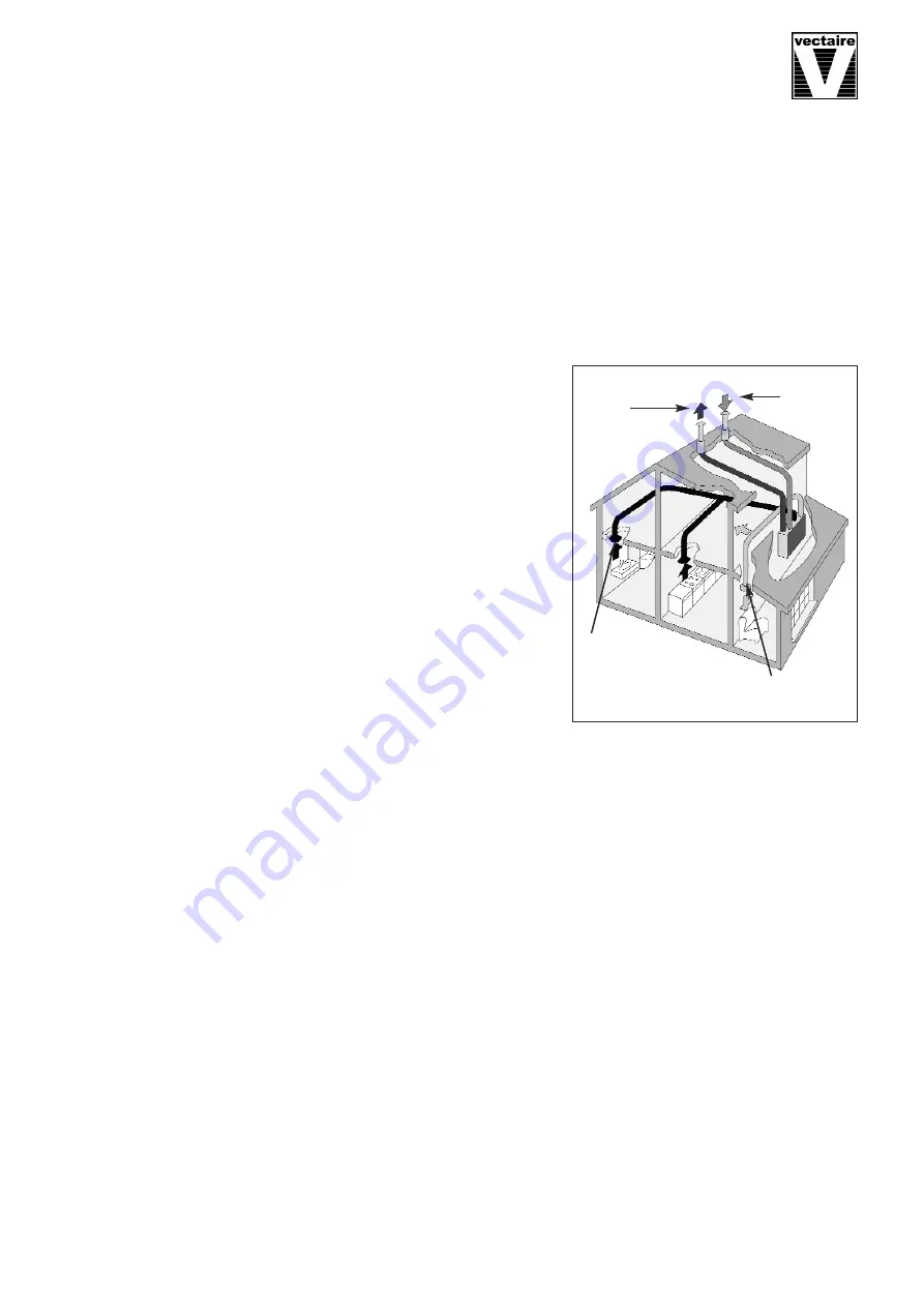
The Vectaire WHHR125DC- Aera heat recovery system provides
whole house mechanical ventilation to living areas, bedrooms, kitchen
and bathrooms. It extracts stale, contaminated air from kitchens,
utility rooms and bathrooms, and uses the heat recovered from this
air to warm fresh, incoming air to create a flow of fresh, filtered air
throughout the dwelling. The extract and intake air streams are
separated to avoid contamination.
The majority of the heat is reclaimed from extracted air and used, via
the heat exchange process, to warm incoming fresh air. The system
will operate continuously to create a stable, comfortable, healthy
environment avoiding the use of excessive energy and saving heat
already generated.
The heat recovery unit must be installed vertically, and will generally be
sited in the loft of a house or the void above the ceiling in an
apartment, or in a cupboard. It will be connected by hidden ductwork
to vents sited in the ceilings of the rooms which are to be ventilated.
Each unit is commissioned individually so that the amount of air moved is tailored to suit the performance
required. There will be a facility to boost the extraction rate when desired (e.g when cooking or bathing, or
when pollutant levels rise). This may be done automatically or manually.
The system is designed to run continuously and should NOT be switched off except for maintenance or filter
replacement. It is important to follow the advice in this user manual and correctly install and maintain the
system to ensure a healthy and comfortable indoor environment.
Features
• SAP Q Eligible
whole house heat recovery units giving continuous ventilation in the kitchen and up to six
additional wet rooms (using rigid ducting)
•
low noise levels
•
variable choice low (trickle) speed and boost options for optimum setting at installation
•
boost speed can be triggered by a switched live connection from a variety of external devices including:
- PIRFF (passive infra red)
*
- DRH240 (dynamic remote humidistat)
*
- THM (thermostat)
*
- a light switch (if more than one light switch is used,
each one must be a double pole switch)
- a remote switch/pull cord
(
*
PIRFF, DRH240 and THM may have integral over-run timer which controls the length of time that the fan
will continue to operate at its boost speed after the boost has been switched off.)
•
Installation MUST be carried out by suitably qualified personnel and MUST be in accordance with current IEE
regulations
Incoming
fresh air
Warmed
fresh air
Cooled
outgoing
stale air
Outgoing stale air


