


Page 7
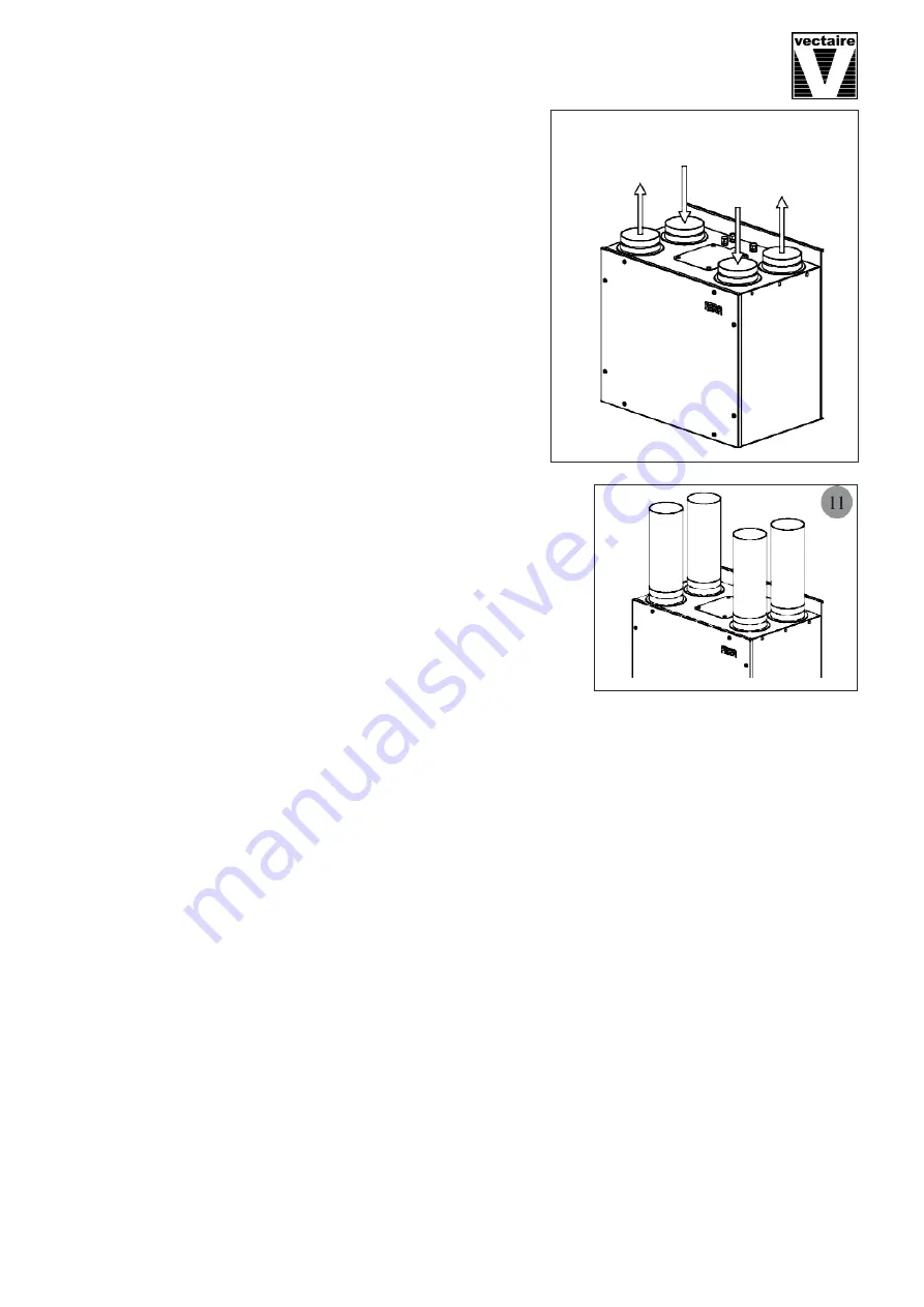
Duct and Duct Connections
(refer to design drawing)
•
4 x 125mm nominal diameter spigots are provided for the
connection of ducting. These are clearly marked for correct
connection of the supply and exhaust ducts.
•
Where ducts are exposed in unheated areas, they should be
insulated (except for the exhaust duct from the unit to the
atmosphere),
•
The duct layout must be designed to suit the requirements of the
ventilation/heat recovery system and building layout.
•
Where rigid duct is used, it should be installed using the least
number of fittings to minimise air flow resist ance. Where
possible, final connection to the grilles and unit should be made
with a flexible connection.
•
Where flexible ducts are used, ensure that:
- lengths of ducting longer than necessary are
not
used
- the duct is stretched so that it is smooth and straight
- where bends are necessary, they have large radii (ie avoid
sharp bends)
- the duct is not crushed if in a restricted area
•
Where ducting passes through a fire partition, suitable fire
dampers
must
be installed to prevent the transmission of fire
through the duct.
.
Electrical Connection
WARNING: these appliances must be earthed and all wiring must conform to current IEE Regulations and all
applicable standards and Building Regulations.
• The unit is suitable for 230V, 50Hz Single phase supply fused at 3A.
• The unit is supplied with a mains rated 4 core flexible cord (black, brown, grey and green/yellow)
• A triple pole isolation switch with contact separation of at least 3mm must be used to connect the appliance
to the fixed wiring when using the Switched Live.
• Boost controls must not be located within 1 metre of a cooker or where they may be affected by excessive
heat or moisture,
• Boost controls should be clearly identified and conveniently located.
• The boost switch wiring cable access is via a 12mm cable gland.
•
boost speed can be triggered by a switched live connection from a variety of external devices including:
- PIRFF (passive infra red)
*
- DRH240 (dynamic remote humidistat)
*
- THM (thermostat)
*
- a light switch (if more than one light switch is used,
each one must be a double pole switch)
- a remote switch/pull cord
(
*
PIRFF, DRH240 and THM may have integral over-run timer which controls the length of time that the fan
will continue to operate at its boost speed after the boost has been switched off.)
Incoming
fresh air
Cooled
outgoing
stale air
Fresh
air out
Stale
air in


