background image

Page 8

Commissioning

   The unit operates by extracting warm, stale air from kitchens, WCs, 

    bathrooms etc, and passing it through  a heat exchanger to the 
    outside.  Another fan draws in cool, fresh air and passes it through the
    same heat exchanger, where it heated by the outgoing, stale air (the 
    air flows do not mix).

   When the unit is set up and running, the minimum setting on the 

    speed control switch must relate to the designed volume air flow.  
    The variable air flow from minimum to maximum allows the unit to 
    extract a greater volume to cope with any increase in the build up of 
    condensation or foul air, ie cooking etc.

   Before starting the commissioning procedure, refer to the design rating  for correct air flows.

N.B

extract and supply air volumes will not always be equal.  When setting up, therefore, the extract system should

be the datum.

Commissioning Procedure

   Ensure that the exhaust and supply grilles or valves are open.

   Turn the electrical supply ON and set the fan speed control to TRICKLE.  

   Check the air flows at the grilles or valves, and adjust to suit the design figures by turning the centre of the 

    valve clockwise to decrease the airflow, and anticlockwise to increase the airflow.

   If the airflow is still not correct proceed as follows:

    -    turn the electrical supply OFF
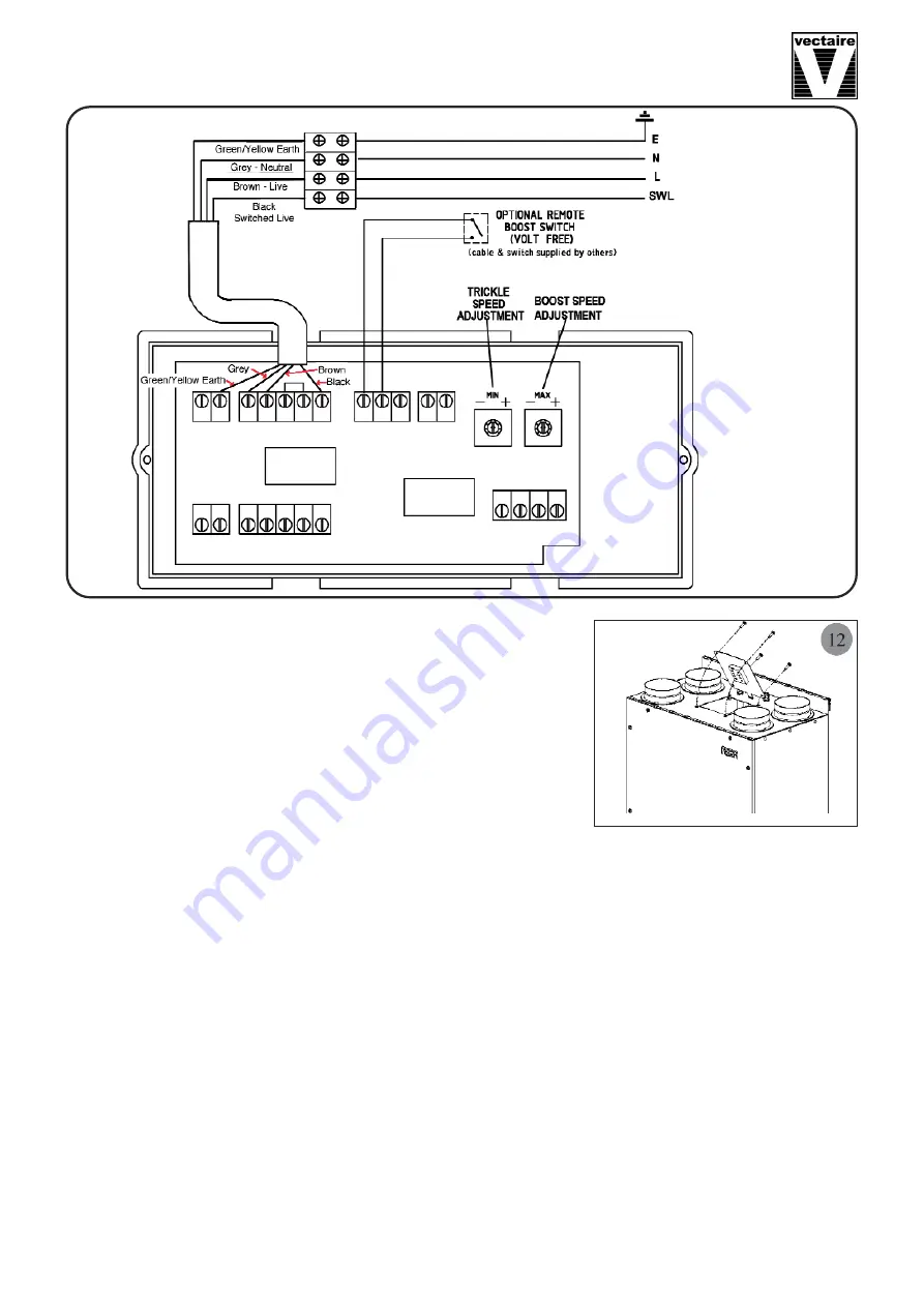
    -    remove the electrical cover
    -    locate the trickle speed adjustment (see Wiring Diagram above) and adjust as required.  
    -    turn the electrical supply ON.

   Re-measure the air flows at the grilles or valves as detailed above, and repeat the procedure until the correct

    air flows are achieved.

   Switch the fan speed to boost and ensure that airflows increase.  Adjust the "Boost Speed" setting to the

    desired value.

Summary of Contents for WHHR125DC

Page 1: ...WHHR125DC Aera Residential Whole House Heat Recovery Unit with Low Energy DC Motor Installation Operating and Maintenance Instructions...

Page 2: ...the loft of a house or the void above the ceiling in an apartment or in a cupboard It will be connected by hidden ductwork to vents sited in the ceilings of the rooms which are to be ventilated Each...

Page 3: ...le or corrosive in ambient temperatures above 40 C or lower than 0 C in areas of excessive humidity or in a wet environment Where possible the unit should NOT be installed directly above a bedroom or...

Page 4: ...l mounting bracket 1 x Safety bracket 2 x 15mm Drain connectors 4 x M6 screws and wall plugs 1 x self tapping screw 1 x Installation Operation Maintenance Instructions Any parts shortages or faults mu...

Page 5: ...he interlocking side is at the top as shown 5 Mount the unit by locating the bracket on the back of the unit securely over the mounting bracket 6 Fix the lower safety bracket as shown Screw and plug s...

Page 6: ...hold drainage system via a U bend which must act as an air lock 7 The unit has two drain condensation outlets with two fittings and bungs to seal off one of the outlets 8 In UK climate conditions the...

Page 7: ...ical Connection WARNING these appliances must be earthed and all wiring must conform to current IEE Regulations and all applicable standards and Building Regulations The unit is suitable for 230V 50Hz...

Page 8: ...volumes will not always be equal When setting up therefore the extract system should be the datum Commissioning Procedure Ensure that the exhaust and supply grilles or valves are open Turn the electri...

Page 9: ...suitably qualified person the frequency of cleaning will vary depending on the installation environment Remove the access panel Slide out the filters that are fitted either side of the heat exchanger...

Reviews: