background image

Vectaire WHHRC180DC

5

Operation Chapter 

4

4.1 Outline description

An appliance from the 

:++5&'&

 series is a highly advan

ced heat recovery unit, specially designed for minimum energy 
consumption and maximum comfort. This is achieved with the 
aid of various electronic control systems. A control unit with mi

croprocessor controls and monitors the safe operation of the 
appliance and ensures that the air quantities remain constant 

and at the preset values. 
The 

:++5&'&

 comes with a control panel with display, ena

bling stepless adjustment of the volume without having to open 
the appliance. Moreover, information regarding the operation 
can be read out from the outside of the appliance.

4.2 LED display system and operating panel

7KH

:++5&'&

LV¿WWHGZLWKDFRQWUROSDQHO,WFDQ

be used to retrieve and modify the settings in the control unit 
program.
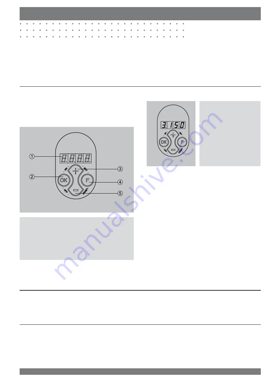
The control panel has four keys and a display.

Control panel 

:++5&'&

1

=

Display

   .H\³2.´FRQ¿UPUHDG\¿OWHULQGLFDWLRQUHVHW

3

=

Key increase parameter

4

=

Function key

5

=

Key decrease parameter

On the left the display indicates the ventilation setting or the 
parameter type. On the right it shows the readout value, for 

LQVWDQFHWKHSUHVHWDLUÀRZ

Example:
The display now shows that the 
appliance is running at ventila

WLRQ VHWWLQJ  DW D ÀRZ UDWH RI

150 m

3

/h.

The 4 keys have the following functions:
• F   

Function key / switching on and off parameter menu 

• +   

Next parameter / increase value

‡ 

3UHYLRXVSDUDPHWHUGHFUHDVHYDOXH

• OK

Switching on and off settings menu / manual fault reset 

¿OWHULQGLFDWLRQUHVHW

Other commands can be entered with key combinations.

‡) VHW

FRQ¿UPSDUDPHWHUYDOXH

‡) UHVHW

UHVHWSDUDPHWHUYDOXHWRIDFWRU\


setting

• OK & + (ON),

switch on appliance

‡2. 2)) VZLWFKRIIDSSOLDQFH

Everywhere in this booklet it applies that when a key has to be 
pressed, the key in question is printed in quotation marks and 
in bold.

([DPSOHSUHVVNH\³

OK”

4.3 Frost protection

The frost protection system ensures that the secondary side 
of the heat exchanger (outlet side) does not freeze up by in

WURGXFLQJDQLPEDODQFHEHWZHHQWKHLQOHWDQGRXWOHWDLUÀRZV

dependent on the outside air temperature and the pressure 
across the heat exchanger.

4.4 Filter indication

7KHDSSOLDQFHLV¿WWHGZLWKD¿OWHULQGLFDWLRQV\VWHP,WLQGLFDWHV
RQWKHGLVSOD\ZKHQWKH¿OWHULVIRXOHG

For more detailed information refer to sections 7.2 and 8.1

Summary of Contents for WHHRC180DC

Page 1: ...le house heat recovery units for homes continuous ventilation in kitchen and up to 4 additional wet rooms airflow at 150Pa 180m3 hr suitable for areas up to 150m2 up to 88 of heat is recovered from air extracted from warm moist rooms to create a stable comfortable healthy environment constant flow fans keep air flow rate at same level under all conditions easy to install for fitting into lofts or ...

Page 2: ...sing rigid ducting Exhaust Terminal Config uration Fan Speed Setting Specific Fan Power W l s Heat Exchange Efficiency Energy Saving Trust Best Practice Performance Compliant Kitchen 1 additional wet room 50m3 hr 0 84 88 yes Kitchen 2 additional wet rooms 85m3 hr 0 84 88 yes Kitchen 3 additional wet rooms 110m3 hr 0 91 87 yes Kitchen 4 additional wet rooms 130m3 hr 1 12 84 yes Figures from BRE tes...

Page 3: ...or for domestic and commercial use Installation Operating and Maintenance Instructions Vectaire Ltd Lincoln Road Cressex Business Park High Wycombe Buckinghamshire HP12 3RH Tel 44 0 1494 522333 Fax 44 0 1494 522337 Email sales vectaire co uk WHHRC180DC Sept2010 E O E ...

Page 4: ...tor Connecting the power Connections and dimensions 5 Connections 5 5 5 1 5 2 5 3 5 4 5 5 5 5 1 5 5 2 5 5 3 5 6 5 6 1 6 6 6 6 7 7 7 8 8 9 9 Operation instructions Switching the appliance on and off Setting the air quantity Installer settings Menu structure display Diagram menu structure Readout settings Readout settings by the user Readout settings by the installer Modifying settings Modifying set...

Page 5: ...HRC180DC Table of contents Electric diagrams Basic diagram 5 Wiring diagram 5 9 9 1 9 2 21 21 22 Service Exploded view 5 Service parts 5 10 10 1 10 2 23 23 23 Appendixes Declaration of conformity 24 24 Chapter Page ...

Page 6: ...mpletely new frost protection system that ensures op timum performance of the appliance even at very low at PRVSKHULF WHPSHUDWXUHV QRLVH UHGXFWLRQ GXH WR OLPLWHG SUHVVXUH ÀXFWXDWLRQ The appliance comes ready for use All control equipment has been mounted and checked in the factory On installation the appliance must be connected to the air ducts the condensate discharge the mains supply and the mul...

Page 7: ...ection 5 6 1 for pictures and dimensions of the applian ce 2 2 Technical information 9HFWDLUH 5 Supply voltage V Hz 230 50 Protection degree IP31 Dimensions w x h x d mm 560 x 600 x 315 Duct diameter mm Ø125 External diameter condensate discharge mm Ø20 Weight kg 25 Filter class G3 Fan setting 1 2 3 Ventilation capacity m3 K DFWRU VHWWLQJV 75 100 150 Permissible resistance in the ducting Pa Rated ...

Page 8: ...Fan graph Note The value stated in the circle is the capacity per fan in Watts Fan graph 5 Flow rate m3 h Resistance ducts system Pa 9 13 21 28 43 63 66 25 37 8 17 54 58 12 15 23 31 48 53 0 50 100 150 200 250 300 0 25 50 75 100 125 150 175 200 W x ...

Page 9: ...temperature 6 Communication port RQQHFWLRQV IRU FDEOH WR PXOWLSOH VZLWFK LI GHVLUHG ZLWK OWHU LQGLFDWRU 7 Cable grommet Grommet for feeding through power cable 230 Volt 8 OpenTherm connection 7ZR SROH VFUHZ FRQQHFWRU IRU 2SHQ7KHUP FRQWURO 9 Input fan Feeds fresh air into the dwelling 10 Basic pcb Contains the control electronics for the basic functions 11 Output fan Discharges fouled air from the ...

Page 10: ...tion setting or the parameter type On the right it shows the readout value for LQVWDQFH WKH SUHVHW DLU ÀRZ Example The display now shows that the appliance is running at ventila WLRQ VHWWLQJ DW D ÀRZ UDWH RI 150 m3 h The 4 keys have the following functions F Function key switching on and off parameter menu Next parameter increase value 3UHYLRXV SDUDPHWHU GHFUHDVH YDOXH OK Switching on and off sett...

Page 11: ... LQ WKH URRI VSDFH W RQ DQ DFRXVWLF PDW I ZDOO KXQJ RQ D wall with a mass of less than 200kg m2 additional measu res such as double panelling extra studs or an acoustic mat will be required I UHTXLUHG D PRXQWLQJ VXSSRUW IRU ÀRRU PRXQWLQJ LV DYDLOD ble product code 217031 5 3 Connecting ducts 7KH DLU RXWOHW GRHV QRW KDYH WR EH WWHG ZLWK D FRQWURO YDOYH The appliance itself controls the air volume T...

Page 12: ...i scharge in the desired position in the lower part of the appli ance See the drawing below for an example of a connection to a drainpipe Pour water into the bend to create an air trap if FRQQHFWLQJ WR D VRLO SLSH UHIHU WR ORFDO E H ODZV 5 5 Electric connections The appliance comes ready to be wired into the mains 5 5 1 Connecting the multiple switch The multiple switch supplied as an extra is con...

Page 13: ...er The appliance should be connected to the mains circuit by a TXDOL HG HOHFWULFLDQ 7KH HOHFWULF LQVWDOODWLRQ PXVW FRPSO ZLWK the regulatory requirements Warning The fans and controls carry a high voltage Al ways disconnect from the mains supply when working on the appliance 5 5 2 Connecting the OpenTherm connector Q FRPELQDWLRQ ZLWK GHPDQG FRQWUROOHG YHQWLODWLRQ WKH DS pliance can also be control...

Page 14: ... 5 6 1 Connections9HFWDLUH 5 A Top view B Front view C Side view D Bottom view E Electric connections F Detail wall mounting make sure to correctly place the rubber strip washers and caps G Connection condensate discharge I To dwelling II To atmosphere III From dwelling IV From atmosphere ...

Page 15: ...ly press keys F and UVW F then WR VDYH WKH PRGL HG VHWWLQJ WKH PRGL HG YDOXH ZLOO QRZ EOLQN DV FRQ UPDWLRQ 7KH GLVSOD UHDGRXW ZLOO UHPDLQ DW WKLV PRGL HG YD lue Press key OK to go back to the set WLQJV PHQX LI UHTXLUHG VHYHUDO VHW WLQJV FDQ QRZ EH PRGL HG VHH LWHP to 5 inclusive 5 Now continue with item 6 Chapter 6 Operating instructions 6 1 Switching the appliance on and off 6 2 Setting the air q...

Page 16: ... at the ventilation position set here I3 Not applicable I4 Switch line 1 step Determines what position of the multiple switch matches line 1 on the control unit I5 Switch line 2 step Determines what position of the multiple switch matches line 2 on the control unit I6 Switch line 3 step Determines what position of the multiple switch matches line 3 on the control unit I7 Imbalance permissible This...

Page 17: ... Press key or 3UHVV NH F and OK 3 seconds Activate parameter set installer Press key or 3UHVV NH OK 1 second I QR NH LV RSHUDWHG GXULQJ PLQXWH 3UHVV NH OK 1 second I QR NH LV RSHUDWHG GXULQJ PLQXWH Select parameters VWDQGDUG 8 8 ZLWK RSWLRQ SFE Q D 8 8 Press key OK 1 second to display the selected parameter setting Select parameters VWDQGDUG 8 8 ZLWK RSWLRQ SFE 8 8 Q D 3 3 Press key OK 1 second to...

Page 18: ...ed output volume are shown Operational mode On the left the position of the multiple switch position 1 2 or 3 is shown and to the right of the dot the volume of the output fan is shown a Position multiple switch b Volume output fan 6 5 1 Readout settings by the user The user can read out other relevant data using keys and step 0 to step 6 Step numbers are not shown on the display 6HH WKH WDEOH EHO...

Page 19: ...ss key F and OK for 3 seconds to activate the comprehensive installer parameters set 3 The desired parameter can be found with the aid of keys and during 3 seconds 4 Pressing key OK calls up this setting 5 Use keys and for 3 seconds to modify the value 7KH PRGL HG VHWWLQJ FDQ QRZ EH A saved and stored B removed C restored to factory setting A Simultaneously press keys F and UVW SUHVV F and then VD...

Page 20: ... 3 2 I 4 Switch line 1 step 0 1 2 3 1 I 5 Switch line 2 step 0 1 2 3 2 I 6 Switch line 3 step 0 1 2 3 3 I 7 Imbalance permissible 0 1 1 Yes I 8 n a n a 0 I 9 n a n a 0 I10 Constant pressure switched off 0 1 0 no I11 n a 0 1 2 3 0 I12 n a 0 I13 Filter message on off 1 0 1 on I14 n a 1 0 0 I15 HDW UHFRYHU FRQ JXUDWLRQ 0 1 0 heat recovery I16 Fan off 1 2 3 1 Output fan I17 Repeat time 1 24 24 hours I...

Page 21: ...n question has been solved Then the appliance will reset itself auto reset and the display will once more show operational mode The table to section 7 3 gives an overview of the faults pos sible causes and the actions to be undertaken 7 2 Filter indication If the display shows the message FIL WKHQ WKLV PHDQV WKH O WHUV KDYH WR EH FOHDQHG I D PXOWLSOH VZLWFK ZLWK OWHU LQGLFDWLRQ has been installed ...

Page 22: ... installer Check the wiring from the sensor to the basic pcb Check the sensor connection to the wiring Replace the sensor F10 The temperature sensor that measures the temperature of the output air is defective Contact the installer Check the wiring from the sensor to the basic pcb Check the sensor connection to the wiring Replace the sensor Note If setting 2 does not work with a mechanical rpm con...

Page 23: ...OLDQFH ZLWKRXW OWHUV 3XW WKH ZD VZLWFK DW VHWWLQJ WR OHW WKH DSSOLDQFH V IDQV run at low speed 2SHQ WKH OWHU GRRU 5HPRYH WKH OWHUV 5HPHPEHU LQ ZKDW ZD WKH OWHUV DUH taken out 8VH D YDFXXP FOHDQHU WR FOHDQ WKH OWHUV 3ODFH WKH OWHUV EDFN WKH VDPH ZD DV WKH ZHUH WDNHQ RXW ORVH WKH OWHU GRRU IWHU FOHDQLQJ WKH OWHU RU WWLQJ D QHZ OWHU WKH OWHU LQGLFD tion must be reset by pressing key OK for 1 second 7...

Page 24: ...h off the appliance on the control panel simultaneously press keys OK and for 3 seconds and switch off the power supply 2SHQ WKH OWHU GRRU 5HPRYH WKH OWHUV 3 Remove the move the front cover 4 Remove the heat exchanger Be careful not to damage the foam parts in the appliance 5 Clean the heat exchanger using hot water 55 C max and a regular detergent Rinse the exchanger with hot water 6 Remove the c...

Page 25: ...e fan unit 12 Place the fan unit back in the appliance 13 Place the earth wire back and replace the connectors that were pulled 14 Replace the control panel 15 Replace the heat exchanger back into the appliance 16 Replace the front cover 3ODFH WKH OWHUV EDFN LQWR WKH DSSOLDQFH ZLWK WKH FOHDQ VLGH facing the exchanger ORVH WKH OWHU GRRU 19 Switch on the power supply 20 Switch on the appliance on th...

Page 26: ...rams Chapter 9 9 1 Basic diagramVectaire WHHRC180DC Maximum 24V50mA Input fan output fan indoor temperature sensor n c n c outdoor temperature sensor n c n a 230 Vac 50 Hz BASIC PCB RNV 04 n a n a control panel OpenTherm connector ...

Page 27: ...HRC180DC ZD VZLWFK B OpenTherm connector C Interior temperature sensor D Basic pcb E Input fan F Output fan G Control panel H Atmospheric temperature sensor 1 Absence mode 2 Presence mode 3 Cooking showering mode C1 brown C2 blue C3 green yellow C5 white C9 red C10 yellow ...

Page 28: ...008 Part Fan Product code 531496 Quantity 1 NOTE Appliance type serial number and year of production are sta WHG RQ WKH LGHQWL FDWLRQ SODWH RQ WRS RI WKH DSSOLDQFH 10 2 Spare parts Vectaire WHHRC180DC No Article description Product code 1 Filter kit 531525 2 Fan 531496 3 Basic pcb 531497 4 Temperature sensor 531451 5 Heat exchanger 531498 6 Installation instructions 611863 7 Control panel with dis...

Page 29: ...tive ROHS 2002 95 EC and the EMC directive 89 336 EC Vectaire Ltd warrants that the Vectaire WHHRC180DC heat recovery appliances are manufactured from high quality materials and that continuous quality control ensures that they comply with the above directives Vectaire Ltd Lincoln Road Cressex Business Park High Wycombe Buckinghamshire HP12 3RH Tel 44 0 1494 522333 Fax 44 0 1494 522337 Email sales...

Reviews: