Vectaire WHHRC180DC
7
Installation Chapter
5
5.4 Connecting the condensate discharge
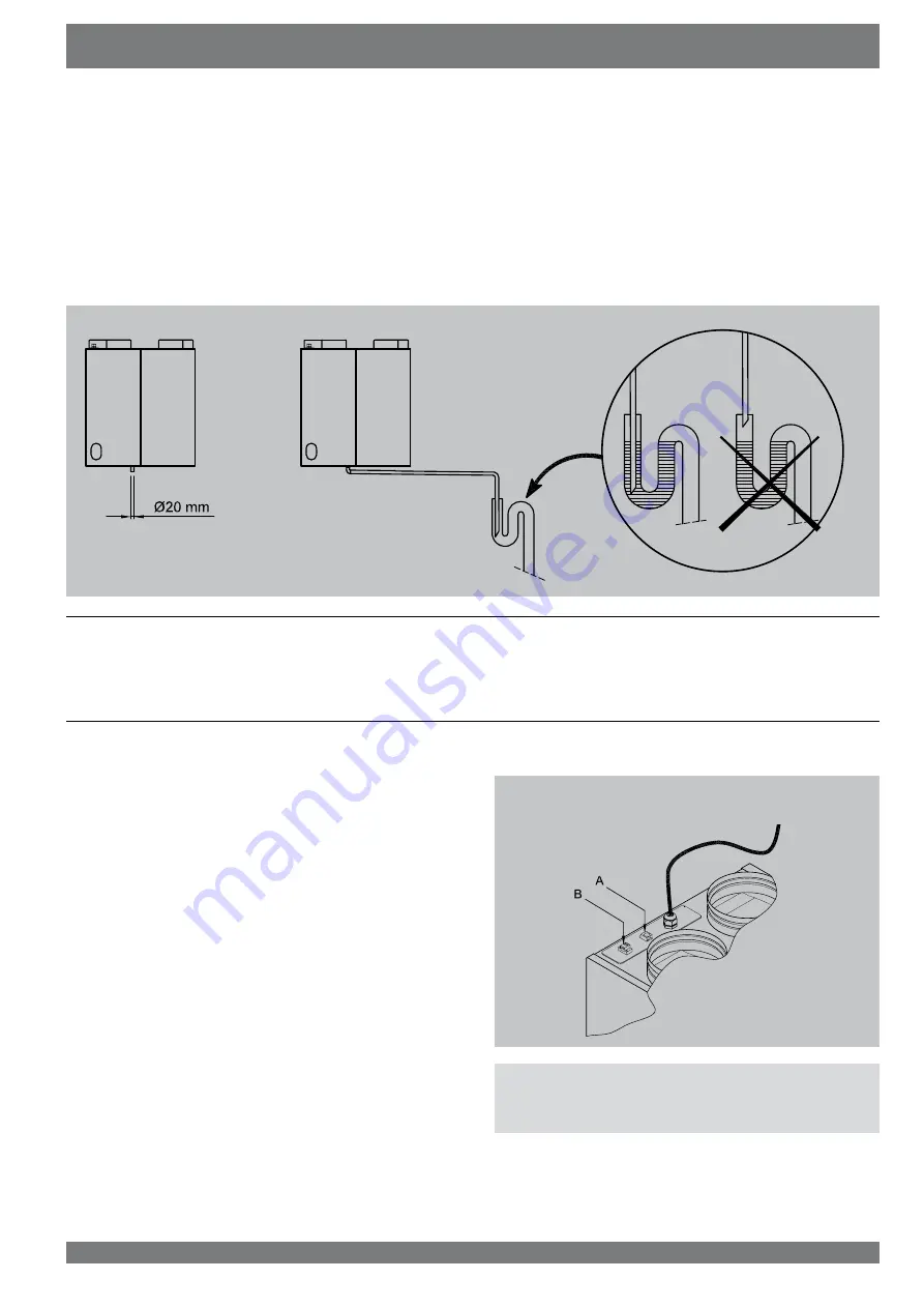
The condensate discharge line for the
:++5&'&
is fed throu
gh the lower panel. The condensate must be discharged throu
gh a drainpipe. The drain must discharge under the water level
LQWKH8WUDS7KHFRQGHQVDWHGLVFKDUJHFRPHVVHSDUDWHO\LQ
the packaging with the appliance and the installer must screw it
into the underside of the appliance. This condensate discharge
connection has an external connecting diameter of 20 mm.
The condensate discharge line can be glued to it, if necessary
using a 90° bend. The installer can glue the condensate di
scharge in the desired position in the lower part of the appli
ance.
See the drawing below for an example of a connection to a
drainpipe. (Pour water into the bend to create an air trap, if
FRQQHFWLQJWRDVRLOSLSHUHIHUWRORFDOE\HODZV
5.5 Electric connections
The appliance comes ready to be wired into the mains.
5.5.1 Connecting the multiple switch
The multiple switch (supplied as an extra) is connected to the
modular connector type RJ12 that is placed at the top of the
DSSOLDQFH6HH¿JXUH$RSSRVLWH
$SSOLFDWLRQRIDZD\VZLWFKZLWK¿OWHULQGLFDWLRQLQDOOFD
VHV UHTXLUHV DQ 5- SOXJ LQ FRPELQDWLRQ ZLWK D FRUH
modular cable.
Refer to the next page for examples of wiring diagrams.
&RQQHFWRU%LVDSROHVFUHZFRQQHFWRUZKLFKLVXVHGLQFRP
ELQDWLRQZLWKGHPDQGFRQWUROOHGYHQWLODWLRQ
$
A = Modular connector
B = OpenTherm connector


