

P L E A S E R E A D T H E F O L L O W I N G I N S T R U C T I O N S V E R Y C A R E F U L LY B E F O R E
U S I N G T H E P R O D U C T. T H E M A N U FA C T U R E R W I L L N O T B E H E L D R E S P O N S I B L E
A N D D E C L I N E S A N Y A N D A L L L I A B I L I T Y F O R D A M A G E C A U S E D T O P E R S O N S O R
P R O P E R T Y D U E T O I M P R O P E R U S E W I T H R E F E R E N C E T O T H E P R E C A U T I O N S
O U T L I N E D I N T H I S M A N U A L .
T H I S M A N U A L M U S T A LWAY S B E R E A D I LY AVA I L A B L E .
THE RANGE
XM10, XM12, XM15, XM10SS, XM12SS, XM15SS: ("A" with automatic front shutter)
4"/10cm,
5"/12cm and 6"/15cm white or stainless steel.
XM10T, XM12T, XM15T, XM10TSS, XM12TSS, XM15TSS
:
("A" with automatic front shutter)
4"/10cm, 5"/12cm and 6"/15cm white or stainless steel and integral overrun timer - the fan should be
operated by a remote switch which can also serve to switch the room light on and off. After the light
is switched off, the fan will continue to operate for a minimum of 3 minutes (adjustable to a maximum
of 15 minutes by turning the red trimmer (4) in a clockwise direction.
XM10H, XM12H, XM15H, XM10HSS, XM12HSS, XM15HSS
:
("A" with automatic front shutter)
4"/10cm, 5"/12cm and 6"/15cm white or stainless steel, integral humidistat and overrun timer - the
adjustable, electronic humidistat is pre-set so that the fan will operate automatically when the moisture
content in the room reaches a pre-set level of relative humidity. The fan will continue to run until the
relative humidity falls below the pre-set level. This level can be adjusted by turning the blue trimmer
(5) on the fan. This fan can be operated by a remote switch allowing operation of the fan independent-
ly of the humidistat (the neon indicator on the front will light when the fan is operating in this mode).
The overrun timer which will
always
make the fan continue to operate for the pre-set length of time
even after it has been manually switched off, can be adjusted as described above.
All fans are 230v: 10cm/12cm/15cm sizes are respectively 15/20/25w with an extract capacity of
98/190/320m
3
/hr (27/53/89 litres/second), pressure of 3/5/8mm H
2
O and a 37/39/41 dbA level. They
are all splashproof to IPX4.
IMPORTANT - SITING INFORMATION
1.
For optimum use your fan should be installed at a minimum height of 2.3 metres.
2.
The fan must not be used in an ambient temperature higher than 40
O
C.
3.
Your fan must not be exhausted into a duct which is already used for any other purpose.
4.
An adequate supply of fresh air must be provided if the fan is to be fitted into a room containing a
fuel burning appliance which is not of the balanced flue type.
5.
Installation must be carried out by qualified personnel. Incorrect installation can cause damage to
people, animals or property for which the manufacturer cannot be held responsible.
6.
If you have any doubts concerning this product, please contact your supplier.
IMPORTANT - ELECTRICAL INFORMATION
1.
All electrical connections must comply with current IEE wiring regulations. The fan is a fixed appli
ance, and the electrical supply must therefore be by a fixed wired and fused (3 amp) spur incorpo
rating a double pole switch with contact openings of at least 3mm. Use twin conductor cable of at
least 1mm
3
in section.
2.
Your fan is double insulated and does not require earthing.
3.
The fan complies with current electrical safety regulations, including EEC Directive EMC89/336
concerning the suppression of radio interference and electromagnetic compatibility.
4.
It is recommended that the installation be carried out by a qualified electrician.
5.
The printed circuit board in these fans has been protected to make it compatible with the majority
of fluorescent fittings available on the market today. However, it is impossible to be aware of all
new products introduced. We suggest, therefore, that you contact your supplier supplier to estab-
lish the compatibility of any fluorescent fittings you intend to use.
INSTALLATION INSTRUCTIONS
1.
Remove all packing material and check that your fan has not been damaged in transit.
2.
Check that your electrical voltage and frequency correspond with those marked on the fan rating
label.
3.
Check the location of existing wiring for ease of connection and make the electrical connections as
in the following instructions.
4.
Cut a 100/120/150mm hole in the wall or ceiling where the fan is to be installed. If nec essary
allow extra space for any ducting used.
5.
Remove the Front Cover (A) (
on the "Automatic" versions this is done by using a gentle,
anti-clockwise twisting action).
6.
Fit the spigot (D) into the hole already cut.
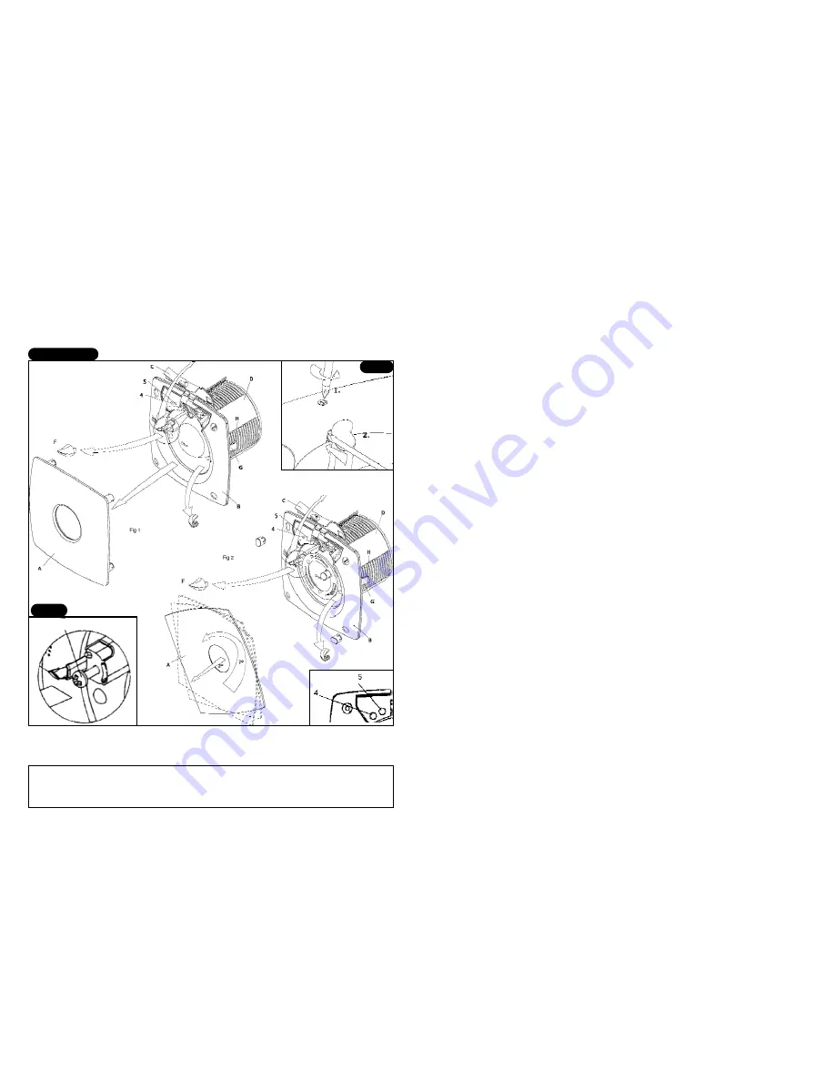
Figs 1 and 2
Fan Exploded Diagram
A. Front cover
B. Housing
C. Connection
cover
D. Spigot
E. Quickfit screws
F. Screw covers
H. Housing
G. Clips
4. Timer trimmer
5. Humidity control
trimmer
Fig 3
Connection Cover (C)
Fig 4
E - quickfit screws


