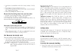
1.
Turn the nut (1) counterclockwise and remove the tip enclosure (2), the tip
(3).
2.
Turn the nipple (4) counterclockwise and remove it.
3.
Pull both the heating element (6) and the cord assembly (11) out of the handle
(12). (Toward the tip of the iron).
4.
Pull out the grounding spring from the “D”-type.
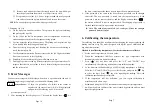
Measure when the heating element is at room temperature
1.
Resistance value of heating element (Red): 3~4
Ω
(Ceramic heater).
2.
Resistance value of sensor (Blue) : 43
~
58
Ω
(Ceramic Heater).
If the resistance value is not normal, replace the heating element (Refer to the
instructions included with the replacement part.)
Sensor (Blue)
Heating Element (Red)
After replacing the heating element
1.
Measure the resistance value between 1) pins 4 & 1 or 6, 2) pins 5 & 1 or 6. If
it is not
∞
, the heating element and sensor are touching. This will damage the
PCB.
2.
Measure the resistance value „a‟, „b‟, and „c‟ to confirm that the leads are not
twisted and that the grounding wire is properly connected.
10.2 Measure the handle cord
There are two methods of testing the soldering iron cord.
1.
Turn the unit ON and set the temperature at highest. Then wiggle and kink the
iron cord at various locations along its length, including in the strain relief area. If
the LED heater lamp flickers, then the cord needs to be replaced.
CAUTION:
Although the iron is in normal condition, when it reaches the
highest centigrade temperature, the indicator LED lamp of
heater will flash.
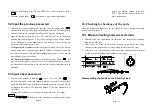
keys are used to select the value.
Temperature rising:
Press UP key directly. If so, the setting temperature will
raise 1
℃
and the display window will display the set temperature. When loose
the UP key, the display window will delay the set temperature about 2 seconds. If
within 2 seconds of time, press the UP key again, the setting temperature will
raise 1
℃
again. If press the UP key and not loose at least 1 second, the setting
temperature will rise rapidly till the needed temperature reaches, then loose the
UP key.
Temperature dropping:
Press DOWN key directly. If so, the setting
temperature will drop 1
℃
and the display window will display the set
temperature. When loose the DOWN key, the display window will delay the set
temperature about 2 seconds. If 2 seconds later, press the DOWN key again, the
setting temperature will drop 1
℃
again. If press the DOWN key and not loose at
least 1 second, the setting temperature will drop rapidly till the needed
temperature reaches, then loose the DOWN key.
4.4 Operation
Connect all the cords referring to the “4.2 connection”. After that press the “UP”
or “DOWM” key to set the temperature (refer to the “4.3 temperature setting”).
And then it can begin to use the soldering station.
5. Password setting
The initial password in station‟s memory is 000. The temperature setting is
admitted in this state. If need to restrict setting the temperature, the password must
be changed.
5.1 Enter into password setting
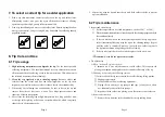
1.
Turn off the power switch. Press and hold the UP and DOWN keys
simultaneously, and then turn on the power switch.
Page 5
Page 12


