background image

24 

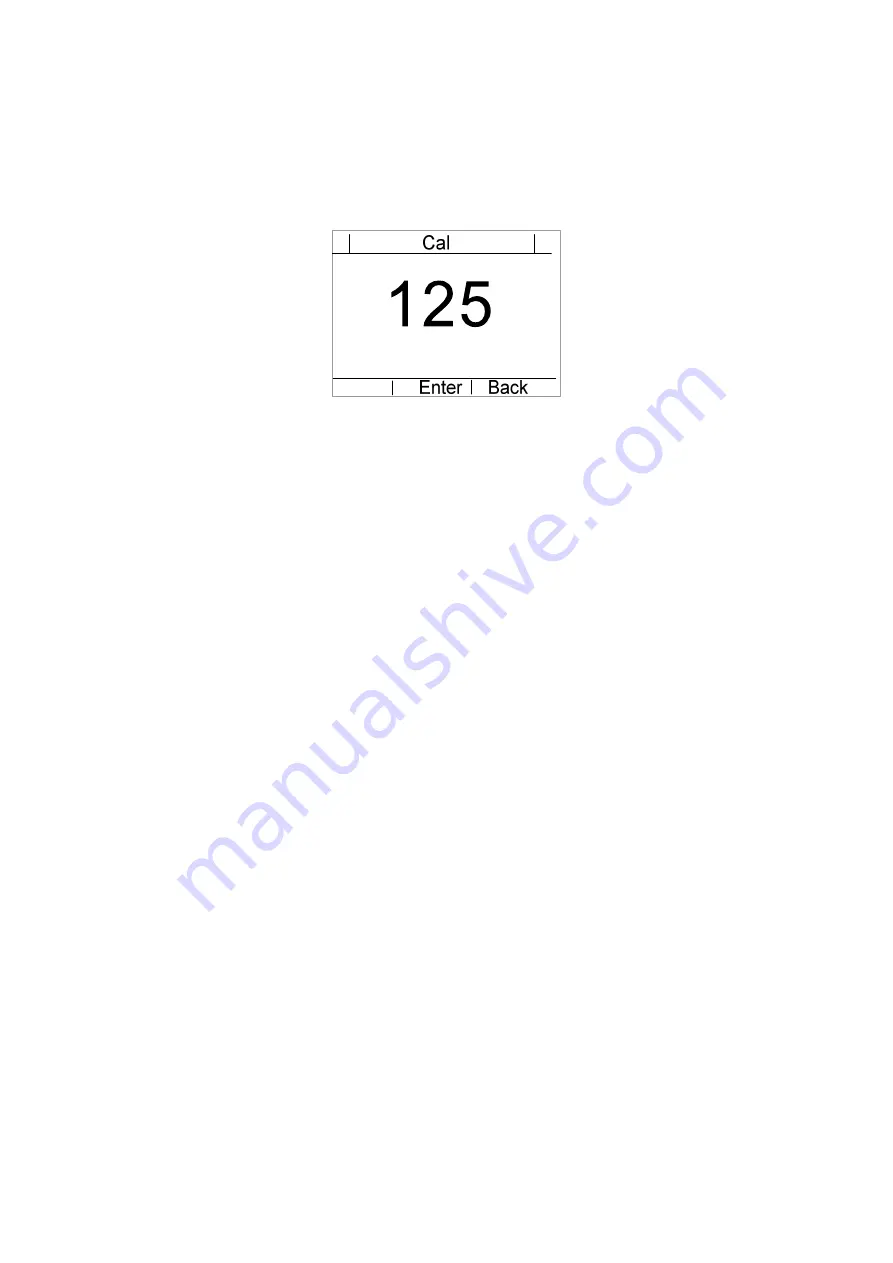
5.3  Calibration Menu


In 

Main

 menu, press “

ORG

” key for 10s to enter into calibration menu, refer to 

following picture. 

Press “

+

”or “

-

” key to adjust number, and press “

OK

” key to confirm. If there are a 

Cal OK

” prompt appears, it indicates that the calibration process has been 

finished. 

Summary of Contents for ET9181

Page 1: ...VECTECH ET9181 Desktop Soldering Machine Instruction Manual...

Page 2: ...Thanks for purchasing our product Read this book carefully before operation please store it in a safety and available place for future reference...

Page 3: ...tion and Pin Function 13 4 1Connection 13 4 2Pin Function 13 4 2 1 2 pin Socket Introduction 13 4 2 2 6 pin Socket Introduction 14 5 Menu Introduction 15 5 1Main Menu 15 5 2Setup Menu 16 5 2 1 Tempera...

Page 4: ...3 5 3Calibration Menu 24 6 Commissioning 25 6 1Preparation 25 6 2Installation 25 6 3Beginning Program 25 7 Troubleshooting and Maintenance 30 7 1Troubleshooting 30 7 2Maintenance 30 7 2 1 Wire Feeder...

Page 5: ...the agents manufactures when the system fails to repair Do not plug or unplug cables during power The power cable should be plug when the machine has long time to be used or idle Risk for injury Do no...

Page 6: ...is fixed for example the X axis may be fixed by sheet metal or lines for safety Unfold the packaging before using the machine make sure the movements fixture for example the Z axis may be fixed by sh...

Page 7: ...c feeder device with adjustable soldering parameters and it is easy to be used 2 1 Feature Heat and cool rapidly Equipped with foot pedal Adjustable program speed time tin feeding interval etc Suitabl...

Page 8: ...ion 280W Input voltage 220V AC Temperature range 100 550 Temperature stability 3 Available Tin Dia 0 5 0 6 0 8 1 0 1 2 1 4 1 6 mm Driver mode Motor Feeder type Foot pedal Manual Soldering iron type 90...

Page 9: ...9 2 3 Dimension Front view Left View Unit mm 285 420 265...

Page 10: ...Functional Description 3 1 Introduction Wire feeder device Baseplate Foot pedal LCD Operation keys Soldering iron 2 pin socket 6 pin socket Power socket Tin roll Fume hose connector Z Axis module Tin...

Page 11: ...SET key to save parameters 3 1 In Main menu press ESC key for 3s to reset count 2 In Setup menu press ESC key to back to Main menu 4 1 Press ORG key to move the machine to home position 2 Press ORG ke...

Page 12: ...to continually decrease The Min temperature is 100 2 In Setup menu press key to move the cursor down 7 Heater switch O position indicates heater is ON otherwise is OFF 8 Power switch Turn ON or turn...

Page 13: ...et Introduction 2 Power Socket connect to power supply 3 6 pin Socket connect to soldering iron pins function refers to 4 2 2 6 pin Socket Introduction 4 2 Pin Function 4 2 1 2 pin Socket Introduction...

Page 14: ...14 4 2 2 6 pin Socket Introduction 6 pin socket is connected to soldering iron pins function refers to following table Socket Pin No Description 1 Sensor 2 Sensor 3 GND 4 Heat 5 Heat 6 No connection...

Page 15: ...bol indicates heating Blue symbol indicates cooling Shows the machine is in unlock mode Shows the machine is in lock mode Shows the temperature unit Red indicates the machine is alarming Yellow indica...

Page 16: ...ess 1 In Main menu press SET key to enter into Setup menu 2 Press or key to move the cursor to Temp 3 Press SET key to activate value Blue indicates value can be modified 4 Press or key to adjust temp...

Page 17: ...adjust speed the speed range is 5 300mm s 4 Press SET key to save 5 Press ECS key to back to Main menu 5 2 3 Tin Speed Tin Speed is used to set speed at which the tin moves during feeding process 1 I...

Page 18: ...e soldering starts 1 In Setup menu press or key to move the cursor to Pre tin 2 Press SET key to activate value Blue indicates value can be modified 3 Press or key to adjust length the length range is...

Page 19: ...djust height the height range is 0 50mm 4 Press SET key to save 5 Press ECS key to back to Main menu 5 2 6 Heat Time Heat Time is the amount of time that the tip waits before soldering process 1 In Se...

Page 20: ...just length the length range is 0 10mm 4 Press SET key to save 5 Press ECS key to back to Main menu 5 2 8 Tin Feeding Tin Feeding length when soldering starts 1 In Setup menu press or key to move the...

Page 21: ...odified 3 Press or key to adjust time the time range is 0 10s 4 Press SET key to save 5 Press ECS key to back to Main menu 5 2 10Solder Time Tin back length when soldering finishes 1 In Setup menu pre...

Page 22: ...or key to adjust height the height range is 0 70mm 4 Press SET key to save 5 Press ECS key to back to Main menu 5 2 12Temp Unit The default unit of temperature is 5 2 13Password Password is used to s...

Page 23: ...elect the menu language there are two languages can be selected 1 In Setup menu press or key to move the cursor to Language 2 Press SET key to activate value Blue indicates value can be modified 3 Pre...

Page 24: ...press ORG key for 10s to enter into calibration menu refer to following picture Press or key to adjust number and press OK key to confirm If there are a Cal OK prompt appears it indicates that the ca...

Page 25: ...rts are fixed Check if the power switch is in OFF Check if the Z axis can move Check all cables are connected 6 2 Installation 1 Install the tin 2 Connect and tighten soldering iron cable to 6 pin soc...

Page 26: ...3 Power on the machine 4 Setting parameters 1 Press SET key to enter into Setup menu 2 Temperature setup Press or key to move the cursor to Temp press SET key to enter then press or key to adjust val...

Page 27: ...ess or key to adjust value press SET key to save Press or key to move the cursor to Heat time press SET key to enter then press or key to adjust value press SET key to save Press or key to move the cu...

Page 28: ...y to adjust value press SET key to save Press or key to move the cursor to Tin Speed press SET key to enter then press or key to adjust value press SET key to save Press or key to move the cursor to L...

Page 29: ...29 7 Starting Program Press foot pedal to activate program when the parameters have been set Note If you have any problem during operation please contact us for technical supporting...

Page 30: ...p 1 High temperature would affect decrease the lifetime of soldering tip Set the temperature as per application but as low as possible 2 The oxide and carbide produced by residual flux will damage the...

Page 31: ...d rosin will corrode the tip plating Choose the solder wire with less activated rosin 6 Do not press the soldering tip Much pressure is not helpful for heat conduction Melt the solder wire to create a...

Page 32: ...32...

Reviews: