background image

17

15.Troubleshooting

No.

Error Message

Descriptions

1

Heater Abnormity

Temperature sensor is not connected

or it is inserted in an error position,

re-connect it after power OFF.

2

No handle

1. Soldering tip is not connected.
2. Soldering tip is not suitable for the

station.

3

Handle error

Circuit of soldering tip abnormal,

check if the connection is right or

not, then re-power on.
Replace a new one.

4

Senor Abnormity Heater is damaged, replace a new

one.

5

Soldering Abnormity
Check tip position

1.The soldering tip is not installed or

damaged.
2.Check tip position.

Summary of Contents for S8

Page 1: ...VECTECH S8 Soldering Station Instruction Manual Thank you for purchasing our products Please keep the instruction manual properly for future reference...

Page 2: ......

Page 3: ...Use of Holder and Sponge 6 7 Connection 7 8 Turn On Off 7 9 Temperature Settings 7 10 Menu Settings 8 10 1 Channel Temperature Settings 8 10 2 Temperature Unit Setting 9 10 3 Sleeping Time Setting 9 1...

Page 4: ...10 13 Tip selection 14 11 Temperature Calibration 14 12 Maintenance of Tips 15 13 Selection of Tips 16 14 Troubleshooting 17...

Page 5: ...n t install the product in a place where the surface is easy to shake or be impacted as it may damage the product Don t place the product in places where it may be exposed to rain or moisture The prod...

Page 6: ...ed compact soldering tip 3 Product Characteristics Can preset process parameter in three channels more practical Celsius and Fahrenheit interchangeable ESD design ESD test function available Resistanc...

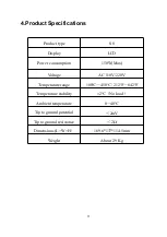
Page 7: ...CD Power consumption 150W Max Voltage AC 110V 220V Temperature range 100 450 212 842 Temperature stability 2 No load Ambient temperature 0 40 Tip to ground potential 2mV Tip to ground resistance 2 Dim...

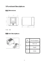
Page 8: ...4 5 Functional Descriptions 5 1 Dimensions Unit mm 5 2 Part Descriptions NO Part Descriptions 1 Main unit 2 Handle 3 Holder...

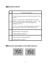
Page 9: ...at the same time on the main interface to enter the menu setting interface Press 1 and 3 keys at the same time to enter the temperature calibration interface 3 Press 1 key on the menu setting interfa...

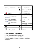
Page 10: ...Descriptions Symbols Descriptions CH0 Temporary channel Black indicates ESD OFF Red indicates ESD ON Heating state interchangeable 1 2 3 1 Indicates the heating state 2 Indicates that the set tempera...

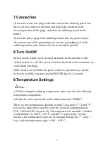
Page 11: ...er switch on the back of the main unit can realize hard switching 2 Soft switch on off After the power switch is powered on it can be turned on or off by long pressing the POWER key for 2 seconds 9 Te...

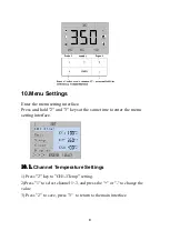
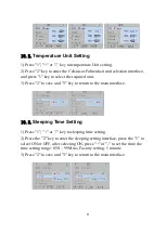
Page 12: ...ld 2 and 3 keys at the same time to enter the menu setting interface 10 1 Channel Temperature Settings 1 Press 2 key to CH1 3Temp setting 2 Press 1 to select channel 1 3 and press the or to change the...

Page 13: ...unit 3 Press 2 to save and 3 key to return to the main interface 10 3 Sleeping Time Setting 1 Press 1 or key to sleeping time setting 2 Press the 2 key to enter the sleeping setting interface press t...

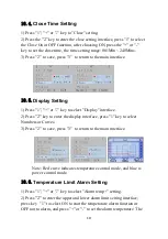
Page 14: ...1 or key to select Display interface 2 Press 2 key to enter the display interface press 1 key to select Numbers or Curves 3 Press 2 to save press 3 to return to the main interface Note Red curve indi...

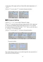
Page 15: ...s 2 to enter the password input setting interface After inputting t he old password 000000 original password press key 2 to enter the new password input interface Press the or key to select the value...

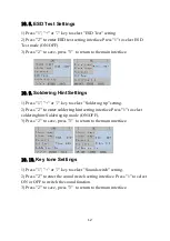
Page 16: ...1 or key to select Soldering tip setting 2 Press 2 to enter soldering hint setting interface Press 1 to select soldering hint Soldering tip mode ON OFF 3 Press 2 to save press 3 to return to the main...

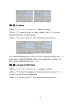
Page 17: ...terface Note After selecting the Safe mode the heat element will heat ups after coperation confirmed if Quick mode is selected the heat element will heat ups immediatelly after power on 10 12 Language...

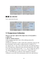
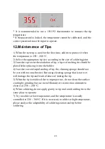
Page 18: ...he temperature of the tip with the thermometer and record the reading value For example 355 3 Long press the 1 and 3 key at the same time the soldering station e nters the temperature calibration mode...

Page 19: ...t into the holder 4 In order to avoid rapid cooling of tip the cleaning sponge should not be wet with too much water But using cleaning sponge that is not wet will damage the tip and lead to failure o...

Page 20: ...the less the temperature drop In addition because the heat capacity of the large tip is higher and relatively low temperature can be used during soldering the tip is not easy to oxidize and the servic...

Page 21: ...No handle 1 Soldering tip is not connected 2 Soldering tip is not suitable for the station 3 Handle error Circuit of soldering tip abnormal check if the connection is right or not then re power on Rep...

Page 22: ......

Page 23: ...purchase date sales company and other items are not completely filled in or the warranty card is altered c Damage caused by failure to follow the use methods and precautions in the manual d Damage ca...

Page 24: ......

Reviews: