
2
SPECIFICATIONS
Model
H100 / H100SF
H200 / H200SF
Motor
Pulse Jet
Pulse Jet
Chemical Tank
Polymer
Stainless steel
Tank Size
4.5L
6.5 L
Flow rate
10-50 LPH
10-50 LPH
Pressure in the chemical tank
0.224 bar
0.224 bar
Fuel
Petrol
Petrol
Performance
19 kW
19 kW
Fuel tank pressure
0.8 bar
0.8 bar
Start
Automatic (manual version available)
Automatic (manual version available)
Fuel tank capacity
1.2 L
1.2 L
Weight(net)
8.5 Kg
10.8 Kg
Dimension
112x30x35 (cm)
135x30x35 (cm)
Features
Short-circuit breaker (tank)
(Model SF : Dual Function – Fog water/oil based
Chemicals)
Short-circuit breaker (tank)
(Model SF : Dual Function – water based
chemicals as well as oil based)
Accessories
Belt, Spares Kit, Charger, Toolkit, Instruction
Manual
Belt, Spares Kit, Charger, Toolkit, Instruction
Manual
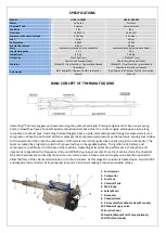
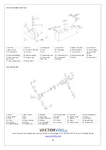
BASIC CONCEPT OF THERMAL FOGGING
VectorFog™ Thermal Foggers are powered using the pulse jet principle. Pulse jet engines don’t have any moving
parts; instead they have a funnel shaped combustion chamber similar to a rocket engine which opens into a long
resonator or exhaust pipe. VectorFog thermal foggers have an auto start and operate through compressed air via a
compressor. When the auto start button is pressed, the compressed air pressurizes the fuel tank, causing fuel to flow
to the injector and then into the carburettor. Air/fuel mixture is then ignited by a spark plug in the carburettor. The
spark is created by an ignition coil which is powered by a rechargeable battery. The ignition coil, battery and
compressor are all housed in the base of the machine. Operating at its optimum performance, combustion and
injection is repeated with a frequency of around 200-250 cycles per second. Once the machine starts, the chemical
tank also becomes pressurized by means of a non-return valve. A close valve and supply valve are then opened to
allow the flow of the chemical/oil solution in to the resonator. At this stage the solution is heated up to around 500C
and dispersed into millions of tiny droplets (around 10 microns) creating a dense and visible smoke.
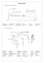
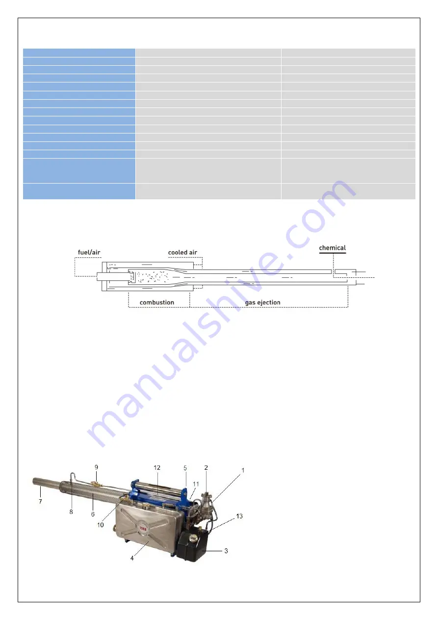
1.
Fuel Injector
2.
Carburettor
3.
Fuel Tank
4.
Chemical Tank
5.
Main Body
6.
Safety Mesh
7.
Resonator
8.
Chemical Inlet
9.
Close valve/Directional valve (SF model)
10.
Chemical Supply valve
11.
Security Cover
12.
Handle/Manual Start Pump (optional)
13.
Off Button (choke)