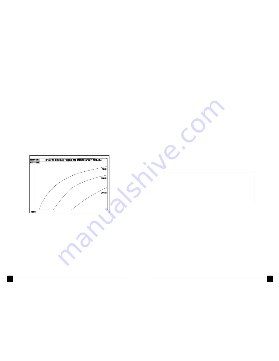
4.3 BATTERY OPERATING TIME
FIGURE 6
is a set of curves that show how appliance load in watts or in
amperes affects operating time. These curves are only estimates of operating
time, dependent upon:
• The condition of the batteries
• The state of charge on the batteries
• The amount of other DC appliances drawing current from the batteries
Three curves were developed for a battery of 50 Ampere Hours (AH)
capacity, and three for multiple batteries in parallel. The higher capacity
curves are for 120 AH and 200AH capacities. These large capacity
batteries clearly extend operating time at full load. To extend operating
time, in general, reduce the heavy appliance load to a minimum.
Remember, you are operating on stored energy and probably under
power loss conditions. All operating time curves assume permanent instal-
lation with the correct DC input wire (#4 AWG) and a full charge on the
batteries.
Figure 6
– Battery Operating Time
For example, as shown in
FIGURE 6
, using a 200 amp hour battery
(batteries) if the average power usage will be 1000 watts the operating
time will be about 150 minutes. A larger capacity battery will deliver
more operating time between recharges.
NOTE:
The manufacturer recommends conservative estimates when
selecting a battery. More amp-hours will deliver a reserve capacity and a
larger capacity battery will not be subject to deep discharges. Ideally, the
number of amp hours you expect to use should be less than 50% of the
battery’s rated capacity.
100
100
1000
1000
90
90
80
80
70
70
60
60
50
50
40
40
30
30
20
20
10
10
900
900
800
800
700
700
600
600
500
500
400
400
300
300
200
200
100
100
15
15
30
30
45
45
60
60
75
75
90
90 105
105 120
120 135
135 150
150 165
165 180
180 195
195 210
210 235
235 240
240
4.4 PROTECTIVE FEATURES
LOW BATTERY ALARM:
An audible alarm will sound when:
1. The 12-VDC power supply voltage drops down to 10.6 volts.
This indicates that the battery needs to be recharged or there is an
excessive voltage drop between the battery power source and the inverter.
NOTE:
It is normal for the alarm to sound the when inverter is being
connected to, or disconnected from, a 12 VDC-power source. This does
NOT indicate a problem. However, if this alarm sounds continuously,
except as described, discontinue inverter operation and recharge the
battery before resuming operation. If the voltage drops to 10.0 VDC, the
inverter will automatically shut down.
If the low voltage alarm sounds when the battery is fully-charged, refer to
the troubleshooting table for possible causes and remedies.
CIRCUIT PROTECTION:
The inverter has electronic circuit protection against overload or short
circuit condition
WARNING:
If turning the front panel mounted
switch OFF then ON does not reset the inverter,
DO NOT ATTEMPT TO OPEN THE INVERTER.
Opening the inverter, for any reason, will void
the warranty. The unit must be returned to Vector
Manufacturing, Ltd. for testing and repair by
professional factory technicians.
12
11


