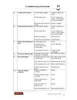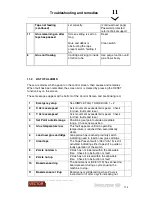
Troubleshooting and remedies
11
________________________________________________________________________________________
_______________________________________
11
-
4
clear of panel.
12
General set required
Machine will not run until General Set
performed.
13
Head Lift Required
Z Axis down and needs to be lifted to set for a
cycle.
14
X Axis negative limit
Axis limit reached during cycle. Reset cycle
and move panel within machine limits
15
X Axis positive limit
Axis limit reached during cycle. Reset cycle
and move panel within machine limits
16
Y Axis negative limit
Axis limit reached during cycle. Reset cycle
and move panel within machine limits
17
Y Axis positive limit
Axis limit reached during cycle. Reset cycle
and move panel within machine limits
18
C Axis CW limit
Axis limit reached during cycle. Reset cycle
and move panel within machine limits
19
C Axis CCW limit
Axis limit reached during cycle. Reset cycle
and move panel within machine limits
20
Tape not cut!
Tape still present in sensor after run on after
end of cycle.
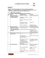
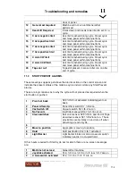
11.3
START PREVENT ALARMS.
These messages appear just above the alarm section on the control screen and
indicate the present status of the machine cycle and also state any Start Prevent
alarms.
These are logic reasons as to why the cycle will not proceed as required when the
start button is pushed.
1
Pivot not back
S23 %I5.9 not activated indicating pivot not
back.
2
Panel Lifters Up
Panel lifter switch S17 %I5.3 on
3
Vac Switch Off
Vacuum switch S3 %I5.2 not on
4
No Vacuum
Insufficient vacuum S47 %I1.15 not on
5
Clean switches
Butt Joint sensor S29 %I5.14 and End of Tape
slow down sensor S31 %I5.26 not on. These
proximities are normally on and turn off when
activating at end of cycle.
6
7
Move to position
Aggregate is moving to position
8
Hold
Hold pushbutton S12 %I5.1 activated
9
Light Barrier
Light barrier broken or zone crossover switch
indicates head is in occupied field.
Other inputs required for Start Cycle but for which there are no screen messages
are:
1
Machine not zeroed
General Set machine
2
Joystick activated
S13, %I1.4 or %I1.5 or %I1.6 or %I1.7 are on
3
C Axis switch activated
S12, %I1.10 or %I1.11 are on
Summary of Contents for Revolution 180
Page 1: ...Operating Manual...

