Assembly
5
________________________________________________________________________________________
_______________________________________
5
-
14
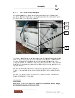
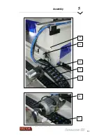
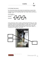
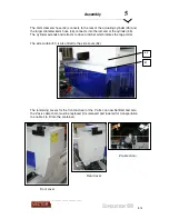
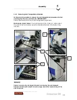
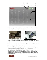
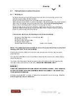
Once the axis brackets are removed and all electrical connections are made by a
qualified technician, it is now possible to connect power to the machine.
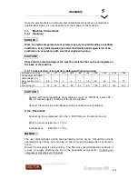
5.3
Machine Connections
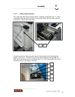
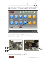
5.3.1 Electrical
Work on electrical equipment or systems may only be performed by a qualified
electrician, or by trained personnel under the direction and supervision of an
electrician, in accordance with electrical engineering rules.
Check that the rated voltage of the machine matches that on the serial plate on
the back of the machine.
5.3.1.1 Cross section of connection cabling and input pre-fusing
Full-load current (A)
<16
<21
<30
<40
<55
<76
<96
<120
<144
<184
Connection: H07/RNF
cable copper (Cu)
Nom. section (mm
2
)
2,5
2,5
4
6
10
16
25
35
50
70
Input
Pre-fusing (A)
20
25
35
50
63
80
100
125
160
200
•
Comply with local regulations and conditions (such as VDE0100, parts 430 +
523, as well as supply conditions of the power supplier)
•
Connect the machine in accordance with the connection circuit diagram.
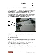
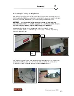
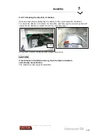
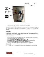
5.3.2 Pneumatic
•
Connect up the compressed air to the ½” BSP fitting on the air service unit
•
Working pressure 6 bar (6 x 10
5
Pa)
•
Limit pressure
8 bar (8 x 10
5
Pa)
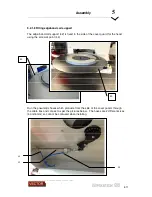
The user units (cylinder, valves) are operated by oil-free dry air. Should the units be
operated at any time by air containing oil, the air must then always be oil enriched in
future.
Ensure the air supply is clean and dry. The filter does not eliminate the possibility of
a poor air supply affecting the life of the pneumatic components. Consult your
compressor manufacturer if in doubt.
DANGER !
CAUTION!
CAUTION !
NOTICE
Summary of Contents for Revolution 180
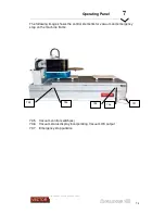
Page 1: ...Operating Manual...


