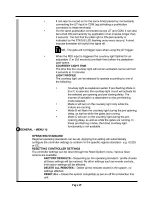
Page 27
Light
Light
Batt +
Batt -
MTR M+
MTR M -
MTR S+
MTR S -
Com
FRX
LIT
LED
Com
Aux 12V
Com Saf
Sol
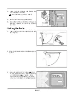
4. Check that the charger and battery are
connected to the controller.
Ensure the battery polarity is correct.
5. Switch on the mains supply (via isolator).
6. Ensure that both the controller and charger are
effectively earthed for improved lightning
protection.
Setting the limits
7. Check that the origin has been correctly set.
(See page 21)
open
8. Check that the gate is closed and the operator is
locked.
9. Push and hold the SETUP button (
) for 3
seconds. Select the “limits” menu by pressing
the ENTER button (
). The Limit setup
wizard will now begin. Follow the on-screen
instructions to complete the setup procedure.
S Sens1
S Sens2
M Sens1
M Sens2
Sens+
Sens-
Safe CLS
Safe OPN
Com
LCK/STP
TRG
PED
3
3
3
3
3
Exit
Go
Up/Dn
Exit
Go
Up/Dn
Exit
Go
Up/Dn
Exit
Go
Up/Dn
Exit
Go
Up/Dn
Exit
Go
Up/Dn
Exit
Go
Up/Dn
Exit
Go
Up/Dn
Exit
Go
Up/Dn
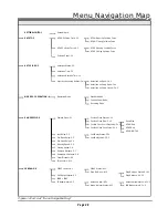
AutoClose
AutoClose
AutoClose
AutoClose
AutoClose
Summary of Contents for V400
Page 1: ...INSTALLATION MANUAL SWING GATE AUTOMATION...
Page 32: ...Page 32 3 4...
Page 36: ...Page 36 7 8 6...
Page 37: ...Page 37 9...
Page 38: ...Page 38 10...
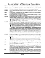
Page 41: ...Page 41 Description of Terminal Functions Description of Terminal Functions...
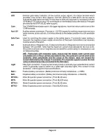
Page 42: ...Page 42...


