background image

VN-200 User Manual 


UM004


www.vectornav.com 

40/47 


5.12.7


SyncOutPulseWidth 

The SyncOutPulseWidth field controls the desired width of the SyncOut pulse. 


Summary of Contents for VN-200

Page 1: ...UM004 User manual VN 200 Beta Rev 0 1 3 1 47 VN 200 User Manual Firmware v0 1 7 x...

Page 2: ...00 SMD Serial UART Interface 10 2 1 3 VN 200 SMD Serial Peripheral Interface SPI 10 2 1 4 VN 200 SMD Reset SyncIn Out and Other General I O Pins 10 2 2 VN 200 Rugged Electrical 11 2 2 1 VN 200 Rugged...

Page 3: ...5 1 User Tag Register 25 5 2 Model Number Register 26 5 3 Hardware Revision Register 27 5 4 Serial Number Register 28 5 5 Firmware Version Register 29 5 6 Serial Baud Rate Register 30 5 7 Async Data...

Page 4: ...ncInSkipFactor 39 5 12 4 SyncOutMode 39 5 12 5 SyncOutPolarity 39 5 12 6 SyncOutSkipFactor 39 5 12 7 SyncOutPulseWidth 40 5 13 Calibrated Sensor Measurements 41 5 14 GPS Configuration 42 5 15 GPS Ante...

Page 5: ...ace mount module Along with providing calibrated inertial sensor measurements the VN 200 also computes and outputs a real time high resolution 3D position velocity and drift free orientation solution...

Page 6: ...Single Power Supply 4 5 to 5 5 V Communication Interface Serial RS 232 TTL 1 5 Surface Mount Development Kit The VN 200 Development Kit provides the VN 200 surface mount sensor installed onto a small...

Page 7: ...ll of the relevant documentation and support software Features 1 VN 200 Rugged Sensor 1 10 foot RS 232 cable 1 6 foot USB connector cable 1 7 Sensor Coordinate System The VN 200 uses a right handed co...

Page 8: ...VN 200 User Manual UM004 www vectornav com 8 47 2 Specifications 2 1 VN 200 Surface Mount Sensor SMD Electrical Figure 2 Pin assignments top down view...

Page 9: ...YNC_IN_2 Reserved for future use For backwards compatibility with older hardware revisions this pin can be configured in software to operate as the time synchronization input signal For new designs it...

Page 10: ...V 0 8 V Input high level voltage 2 V 5 5 V Output low voltage 0 V 0 4 V Output high voltage 2 4 V 3 0 V Clock Frequency 8 MHz 16 MHz Close Rise Fall Time 8 ns 2 1 4 VN 200 SMD Reset SyncIn Out and Oth...

Page 11: ...ADC IMU or attitude measurements are available 5 GND Ground 6 TARE RESTORE Input signal used to zero the attitude of the sensor If high at reset the device will restore to factory default state Inter...

Page 12: ...0 V 5 4 V Output high voltage 5 0 V 5 5 V Output resistance 300 10 M Data rate 1 Mbps Pulse slew 300 ns 2 2 3 VN 200 Rugged Reset SyncIn Out and Other General I O Pins Table 9 NRST Specifications Spec...

Page 13: ...VN 200 User Manual UM004 www vectornav com 13 47 2 3 VN 200 Surface Mount Sensor SMD Dimensions Figure 4 VN 200 PCB Footprint Measurements are in inches...

Page 14: ...200 Rugged Dimensions Figure 5 VN 200 Rugged Dimensions Measurements are in inches 2 5 Absolute Maximum Ratings Table 12 Absolute Maximum Ratings Specification Min Max Input Voltage 0 3 V 5 5 V Operat...

Page 15: ...specific parameters an asterisk a checksum and a newline character An example command is shown below VNRRG 11 73 3 2 Checksum CRC The serial interface provides the option for either an 8 bit checksum...

Page 16: ...start a new communication transaction All binary data is sent to and from the slave with most significant bit MSB first in little endian byte order with pad bytes inserted where required to ensure 16...

Page 17: ...hown as hex No command MISO 00 01 13 00 00 F5 BF BA 00 80 12 38 B8 CC 8D 3B shown as hex Rates 0 001465 0 000035 0 004327 During the first transaction the master sends the command to read register 8 T...

Page 18: ...can be accomplished by sending the same command twice to the VN 200 The response received on the second transaction will contain the most up to date values for the desired register SPI Transaction 1 L...

Page 19: ...ignificant digits from the exponential digits Below are some samples of correct single precision floating point numbers Single Precision Floating Point Number Examples 9 999999E 99 7 344409E 05 1 2345...

Page 20: ...d parameter is the ID of the register to be read The first parameter of the response will contain the same register ID followed by a variable number of parameters The number of parameters and their fo...

Page 21: ...ble 17 Example Write Settings Command Example Command Message UART Command VNWNV 57 UART Response VNWNV 57 SPI Command 8 bytes 03 00 00 00 00 00 00 00 shown as hex SPI Response 8 bytes 00 03 00 00 00...

Page 22: ...atile memory the device will default to factory settings Also upon reset the VN 200 will re initialize its Kalman filter thus the filter will take a few seconds to completely converge on the correct a...

Page 23: ...the received command was invalid Invalid Command 4 The user has requested an invalid command Not Enough Parameters 5 The user did not supply the minimum number of required parameters for the requested...

Page 24: ...of the register in bytes relevant only in SPI mode and the last column provides the Section number where a more detailed explanation of the register may be found Each register may be read or written t...

Page 25: ...Comment User assigned tag register Any values can be assigned to this register They will be stored to flash upon issuing a write settings command Size Bytes 20 Example Serial Read Register Response VN...

Page 26: ...Register Model Number Register ID 1 Firmware v0 1 and up Access Read Only Comment Model Number Size Bytes 24 Example Serial Read Register Response VNRRG 01 VN 200T DEV 77 Byte Offset Name Number Form...

Page 27: ...ision Register Hardware Revision Register Register ID 2 Firmware v0 1 and up Access Read Only Comment Hardware revision Size Bytes 4 Example Serial Read Register Response VNRRG 02 6 6B Byte Offset Nam...

Page 28: ...Register Serial Number Register ID 3 Firmware v0 1 and up Access Read Only Comment Serial Number Size Bytes 12 Example Serial Read Register Response VNRRG 03 0100011981 5D Byte Offset Name Number Form...

Page 29: ...0 1 and up Access Read Only Comment Firmware version Size Bytes 4 Example Serial Read Register Response VNRRG 04 0 1 7 0 73 Byte Offset Name Number Format Unit Description 0 Major Version U1 Major rel...

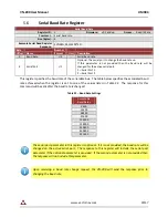
Page 30: ...he serial data bus The table below specifies the associated baud rate achieved when the register is set to one of the values listed in Table 22 The response for this command will be sent after the bau...

Page 31: ...ing Table 23 below lists which registers can be set to asynchronously output the value to specify which register to output and the header of the asynchronous data packet Asynchronous data output can b...

Page 32: ...The serial port to change the asynchronous data type frequency on If this parameter is not provided then the ADOF will be changed for the active serial port 1 Serial Port 1 2 Serial Port 2 Table 24 A...

Page 33: ...reference vectors Size Bytes 24 Example Serial Read Register Response VNRRG 21 1 0 1 8 0 0 9 79375 53 Byte Offset Name Number Format Unit Description 0 MagRefX F4 N A X Axis Magnetic Reference 4 MagRe...

Page 34: ...ect for any orientation errors due to mounting the VN 200 on the user s circuit board The variables are a measured parameter such as acceleration in the body reference frame with respect to the VN 200...

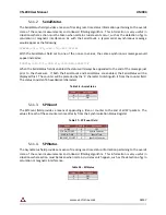
Page 35: ...ions 5 SPIChecksum U1 Choose the type of checksum used for the SPI communications 6 ErrorMode U1 Choose the action taken when errors are generated 5 11 1 SerialCount The SerialCount field provides a m...

Page 36: ...SerialCount and SerialStatus are enabled the SerialStatus will be displayed first The counter will be preceded by the S character to distinguish it from the counter field The status consists of 4 hex...

Page 37: ...checksum used for the SPI communications The checksum is appended to the end of the binary data packet The 16 bit CRC is identical to the one described above for the SerialChecksum Table 30 SPIChecksu...

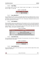
Page 38: ...timing If SyncInMode is set to ASYNC the ADC loop will run on a SyncIn event The relationship between the SyncIn event and a SyncIn trigger is defined by the SyncInEdge and SyncInSkipFactor parameter...

Page 39: ...e pulse when the internal ADC loop starts This mode is used to make a sensor the Master in a multi sensor network array If this is set to IMU mode the pulse will start when IMU measurements become ava...

Page 40: ...VN 200 User Manual UM004 www vectornav com 40 47 5 12 7 SyncOutPulseWidth The SyncOutPulseWidth field controls the desired width of the SyncOut pulse...

Page 41: ...000271 00 021949 20 4 00098 968 58 Byte Offset Name Number Format Unit Description 0 MagX F4 gauss Magnetic X axis measurement 4 MagY F4 gauss Magnetic Y axis measurement 8 MagZ F4 gauss Magnetic Z a...

Page 42: ...d on serial port 2 See table below for available NMEA messages 3 NMEA_Rate U1 GPS NMEA message skip factor If set to 2 then the sensor will send out every other NMEA message NMEA messages are internal...

Page 43: ...er Response VNRRG 57 0 0 0 6D Byte Offset Name Number Format Unit Description 0 PosX F4 m Relative position of GPS antenna X axis 4 PosY F4 m Relative position of GPS antenna Y axis 8 PosZ F4 m Relati...

Page 44: ...pe See table below 11 NumSats U1 Number of GPS satellites used in solution 16 Latitude F8 deg Latitude in degrees 24 Longitude F8 deg Longitude in degrees 32 Altitude F8 m Altitude above ellipsoid WGS...

Page 45: ...th 52 NedVelY F4 m s INS solution velocity in NED frame East 56 NedVelZ F4 m s INS solution velocity in NED frame Down 60 AttUncertainty F4 deg Uncertainty in attitude estimate 64 PosUncertainty F4 m...

Page 46: ...gnal pins Table 40 Factory Default Register Values Settings Name Default Factory Value Serial Baud Rate 115200 Both serial ports Async Data Output Frequency 40 Hz Both serial ports Async Data Output T...

Page 47: ...implied is granted under this document If any part of this document refers to any third party products or services it shall not be deemed a license grant by VectorNav for the use of such third party p...

Reviews: