background image

Vectorworks 2010 Products     75

Vectorworks Spotlight 2010 Getting Started Guide

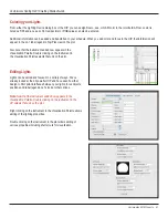
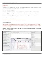
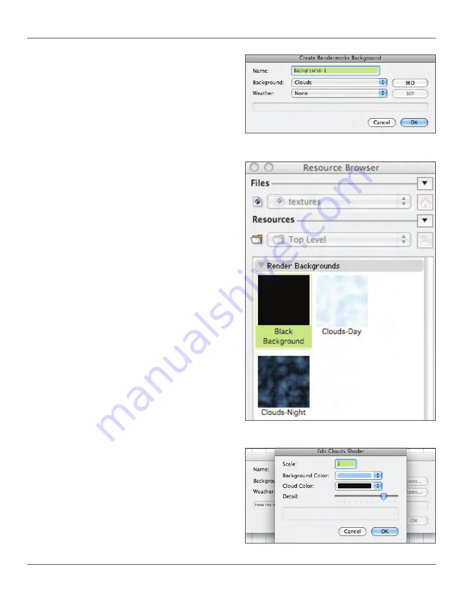
The top drop down will be our focus;

Clouds

• 

One Color

• 

Two Color

• 

Image

• 

Image (HDRI)

• 

 
One color should be pretty clear and having at least                   
a black background is always useful. When roughing out               
ideas, use a black background rather than worrying about the 
surrounding architecture. Two colors will give you a traditional 
gradient background.
 
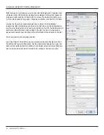
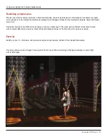
The clouds option is very versatile, certainly useful if you are doing 
an outdoor project or if you want to see a simple outdoor scene 

behind a set. Clouds also make terrific backdrops for free standing 

kiosks. The default options make for a lovely day sky. I have found 
that by switching the white to black, I get a pretty good night sky. As 
always, you need to experiment with the options and render the 
options in Final Quality Renderworks to see your results.

Summary of Contents for 2010

Page 1: ...Vectorworks Spotlight 2010 Getting Started with...

Page 2: ...is a registered trademark of Microsoft Corporation in the U S and other countries Macintosh is a trademark of Apple Computer Inc registered in the U S and other countries Adobe Acrobat and Reader are...

Page 3: ...ng the Drawing 17 Working Planes 19 Locus Points 19 Rotated Views 19 Layer Plane and Screen Plane 20 Understanding Symbols 21 Understanding Symbols 21 Available Resources 21 Creating Symbols 21 Creati...

Page 4: ...D Modeling 44 Manipulating Solids 44 3D Primitives 44 Project The Lighthouse 45 Using the Wall Tools 47 Wall Tool 48 Floors 48 Door and Window Tools 48 Curtain Tool 49 Create Seating Layout 50 Curved...

Page 5: ...and Model View 67 Visualizing your Design 71 Rendering Modes 72 Layer Backgrounds 74 Exercise 76 Textures 77 Creating Textures 77 Assigning Textures 80 Textures and Walls 80 Textures in the OIP 80 Map...

Page 6: ...r Tool 93 Custom Title Blocks 93 Graphic Scale Tool 94 Drawing Labels 94 Viewport Cropping 95 Section Viewports 95 Class Overrides 96 Paperwork 96 NURBS 97 NURBS Tools from the Toolset 97 NURBS Comman...

Page 7: ...the accompanying DVD When I teach Vectorworks I stress the architectural concept of Building Information Modeling BIM Simply put this is working and collaborating in the three dimensional environment...

Page 8: ...and modes Use what works best for you Experiment with different tools and techniques Watch for SmartCursor cues which appear as you hover your cursor over significant drawing object geometry To pan a...

Page 9: ...ation can be automatically updated as information changes The Help Application Window is divided into two columns The left column provides navigation and the right column information If you enter sear...

Page 10: ...uals can be accessed from the Help table of contents Let s take a look at what else comes with the application Some of the terms used here have not been defined as yet we ll get to them but it is impo...

Page 11: ...ette and Resource Browser At the top of the active window you will see the View bar and the Tool Bar The Tool Bar displays different options available for each tool selected from the Basic Tool Set or...

Page 12: ...Favorite Files Navigate to the Vectorworks directory and add the following files toyour favorites Libraries Defaults Renderwoks Textures Textures_Default vwx Libraries Objects Entertainment Lighting...

Page 13: ...ols or plug ins that you would like to add to Vectorworks Some come with their own workspace Other add ons need to be well added on to any workspace where you might want to use them For example lighti...

Page 14: ...s you like You can also edit the contextual menus to readily access an often used tool from the right mouse button From the Tools Tab you can modify your palettes in much the same way You can totally...

Page 15: ...8 x 11 chunks Click OK and now we will begin to make some specific settings Go to File Document Settings Document Preferences you will see three tabs We will leave the left and right tabs set to the...

Page 16: ...ect Interactive and note that you can adjust the cursor and highlighting settings to your liking and by selecting Interactive Appearance Settings you can adjust the selection colors Select User Folder...

Page 17: ...at you can examine my base class structure and another that shows my basic layers needed for every drawing I usually have a tracing layer with a PDF or a JPEG of the theatre ballroom or television stu...

Page 18: ...ve one color and your set wall to have another color By using classes to assign these attributes when the color of the set changes you can change all of the walls at once Similarly you would want diff...

Page 19: ...d a new working plane that angles your working area to the rake angle Multiple raked set pieces at different rakes require multiple working planes Locus Points Vectorworks has two tools for adding loc...

Page 20: ...he opposite of what is written Layer plane will rotate 2D objects in space Screen Plan 2d object will not rotate This can be useful when preparing to extrude an object from 2D into 3D The Layer Plane...

Page 21: ...the unit on stage and in storage Available Resources Go Back to your Vectorworks application directory and look at the many libraries provided You can add more as favorites so their contents can be ac...

Page 22: ...lug in objects can typically only be inserted in the Top Plan View Right click on the symbol in the RB with your test file active click Edit You will then have the option of editing the 2D 3D 3D wall...

Page 23: ...size page your person may only end up as an inch or two tall Here is where this gets a bit tricky I create my figures as actual size in my photo editor So a 6 tall man is a 6 tall image file but I set...

Page 24: ...figures with white and then changed the background so you see a bit of the white outline If you save with a channel or a mask you cannot use the JPEG file format Consider PNG or PSD formats OK now yo...

Page 25: ...ast shadows This is some of the magic in Image Props Auto Rotates allow the prop to always face the camera when rendered You will see how this looks when we finish and you see the IP in plan Select Co...

Page 26: ...collection inserted into a rendering Symbol Types I ve mentioned Plug in Objects a bit Plug in objects PIO or PIO s are like standard symbols but customizable You will see that doors and windows are P...

Page 27: ...ollaboration If one member of the team draws the studio theatre or ballroom space and saves it as a symbol other members of the team can reference that symbol and if it is modified all drawings associ...

Page 28: ...age Props In addition to the people we have just discussed the statuary fountain and fountain water are also all Image Props While these items could have been modeled that process would have added con...

Page 29: ...g As soon as you begin to draw you will note the appearance of the Floating Data Bar FDB Hit the Tab key to select the first field in the FDB and enter a specific dimension tab to the next field repea...

Page 30: ...Align with a corner indicated by the red extension line and hit the T key to lock in that alignment Try this again When hovering near a snap point hit the Z key to enable the snap loupe which allows y...

Page 31: ...0 and y 0 Click OK You will have a square in the middle of the page Double click on the circle tool Enter the following data radius 5 127mm deselect center at next click and enter Ctr x 0 and Ctr y 0...

Page 32: ...lete the circle The square has been clipped by the circle Double click on the circle tool Enter the following data radius 1 2 12 7mm deselect center at next click and enter Ctr x 1 5 38 1mm and Ctr y...

Page 33: ...urrent view drop down menu in the View Bar and or your numeric keypad Interactive Origin Mode Object Center Mode Active Layer Plane Origin Mode Working Plane Origin Mode For our purposes select Object...

Page 34: ...rcles before you may have noticed two similar tools the circle and the oval Let s look at the Oval Tool select it and notice the different options in the Tool Bar Draw a few ovals using the different...

Page 35: ...to quickly duplicate a surface inside or outside of an object Select the tool and go to the tool preferences in the Tool Bar Consider that if you have just drawn some crazy shape that you will use as...

Page 36: ...ol Double click on the rotate tool and any all of your selected objects can be rotated to a specific angle up to 1 100 of a degree You can also freehand rotate by clicking on an object dragging to ano...

Page 37: ...odes Linear Array Rectangular Array Circular Array Note Options for each mode are different but they do allow you to offset in different ways and to rotate the object s that you are duplicating In add...

Page 38: ...e polygon handles Mode Grab a corner and move it around Undo Select the Delete Vertex Mode and delete one of the corners so that you have a rectangle Undo Select Add vertex and be sure that you have t...

Page 39: ...ching a rough of your final object and or using a tracing layer with a placed JPEG or PDF image PDF images created as vector files are especially useful for tracing in Vectorworks as you can snap to p...

Page 40: ...mpler shape I used the Clip Tool Basic Tool Palette to delete enough of the form so that the liquid would not spill This ensures that the inner profile of the glass and the outer profile of the liquid...

Page 41: ...and positioned I go to Model Sweep enter a full 360 and accept the other defaults and almost instant Martini You can add the olive later and once you have seen and explored the 3D Drawing Tools My ex...

Page 42: ...mber yards Vectorworks ships with a library of US nationally available profiles as symbols You can insert one of these symbols and convert to group I added a small piece of wood to hide the edge of th...

Page 43: ...Editing 3D Shapes All of the 3D shapes we have created can be edited or modified by double clicking on the shape At that point you can change the 2D primitives used as the foundation of your form Exer...

Page 44: ...Primitives Hover around the 3D Modeling Tool Set and see what tools are installed Stay away from anything that says NURBS for right now NURBS are complex curves and surfaces which help accomplish ama...

Page 45: ...nge yourself with other great architectural landmarks The United States Government HABS Housing and Building Survey Drawings from the Depression Era WPA is a great resource http memory loc gov ammem c...

Page 46: ...ou do not have to match the original scheme be creative Include a human figure image prop for scale in the rendering and use the human figure 2D symbol in the annotation layers of the section and elev...

Page 47: ...going to assume that zero zero is the intersection of the Plaster Line and the Center Line in a traditional Broadway size proscenium theatre We are not going to worry that our theatre may go off the...

Page 48: ...e SL side Select all the walls and change the wall height Z to 50 15 240m in the OIP Floors Select the Rectangle tool from the Basic Tool Set Click on the USR outside corner of the wall structure and...

Page 49: ...the plaster line With that leg selected go to Edit Duplicate Array and select Linear Array from the drop down menu Make 3 duplicates 5 1 524m on the Y axis Select ALL the legs and then the Mirror Too...

Page 50: ...rectangle selected go to AEC Create Seating Layout Select the padded Theatre Seat and click ok When prompted select the focus straight ahead and seats are automatically created Configure the arrangeme...

Page 51: ...to 6 152 40mm and change its bottom Z to 4 1 219m in the OIP Lastly we need a wall Draw a 2 610m deep by 24 7 315m wide by 20 6 096m tall 21 6 401m US of the plaster line This is a bit boring so we ll...

Page 52: ...s and attach them to your perimeter walls Experiment with these functions at your leisure Select the Column Tool and go to the Preferences in the Tool Bar While it is not yet possible to create a full...

Page 53: ...that in 3D likely from scratch You should be able to create that kind of drawing Soon That s why you re also working on that Lighthouse image while working through this book Be aware here that the do...

Page 54: ...the dialogue and create a stair case Note The choices of available classes in the drop down menus As you have explored the contents of the Vectorworks libraries you will note that there are other sta...

Page 55: ...nu in the view bar to go to the Left view Select the 3D Reshape tool from the 3D Modeling Tool Set select option to add a control point and grab the left side of the wall Note that the cursor changes...

Page 56: ...that can be edited By default you will have a four sided hipped roof Double click on a control point on a side of the roof and select gable repeat on the opposite side An alternate approach like the F...

Page 57: ...some instruments in our document Go to the Resource Browser use the drop down menu look for the little triangle to access the favorite ETC symbols and import the 26 and 50 s 4 s by right clicking and...

Page 58: ...ong version of this guide Click OK Select Edit Layout which will open the Edit Symbol window defined by the colored border From here you can select and drag the labels from the left column around the...

Page 59: ...d select import Revert back to the active document in the resource browser by clicking the Home icon and double click on the 50 pipe to select it Then go to the Spotlight ToolSet and choose the Light...

Page 60: ...age Let s use this opportunity to review creating a hybrid Symbol While a lighting pipe is typically round you can choose to make a round or square simpler geometry smaller file size extrusion 2 50 80...

Page 61: ...isualization Palette Double clicking on the instrument in the Visualization Palette selects that unit on the plot Editing Lights Lights can be edited and focused in a variety of ways We ve already loo...

Page 62: ...ments Add information as you need in the OIP Once you have populated an electric select the Position and check Auto Number in the OIP the instruments will number and that information will be added to...

Page 63: ...ocument or create a custom black and white or full color gobo Any square graphic image can be imported into Vectorworks as a gobo texture Got to Modify Convert Create Gobo Texture and follow the steps...

Page 64: ...d or different fields would be required The principles remain the same Place a 20 6 096m pipe outside of the theatre architecture SL Populate the position with a few lights I started with one unit to...

Page 65: ...ny obstruction issues on the computer and not in the field Photometrics Photogrid The Photometrics and the Photogrid Tools provide you with two ways of ensuring that you have an even wash and that you...

Page 66: ...Criteria Set the criteria as illustrated Note all of the options this is a technique that can be used for many things Once you have all these units selected you can change the color in every one with...

Page 67: ...View command will create a Definition Layer for the boom s selected From that Definition Layer it places a Design Layer Viewport DLVP of the boom s in plan on the Plot Layer this is your 2D Light Plo...

Page 68: ...iew from the View Bar and use the 2D rotate tool to rotate the DLVP If I create each position manually I will create another Definition Layer and DVLP that contains all the other geometry It just won...

Page 69: ...eview them as we move forward but you should make your own design choices All of these files like this plot are relatively simple to allow for ready understanding of the concepts Your work will likely...

Page 70: ...Vectorworks 2010 Products Vectorworks Spotlight 2010 Getting Started Guide I have included the image above to illustrate a scene in this case for A Midsummer Night s Dream lit primarily with custom go...

Page 71: ...be the only path Vectorworks and Renderworks provide a number of ways to visualize your drawings Some of these are pertinent to presenting your mechanical or designer drawings other are relevant to v...

Page 72: ...iew Rendering you will see a list of available rendering modes The View Menu list is longer so let s look at those Wireframe Sketch Sketch Options Open GL Open GL Options Fast Renderworks Fast Renderw...

Page 73: ...useful for fast preview images to see if you have your textures in place and properly oriented I do not see Open GL as a presentation format Open GL can be useful for your own visualization Open GL do...

Page 74: ...a simple object Or you might just not like the basic white background that is the Renderworks Default Let s work in the file you created when you made the 10 3D objects Choose to edit your design lay...

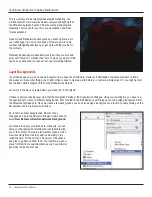
Page 75: ...ding architecture Two colors will give you a traditional gradient background The clouds option is very versatile certainly useful if you are doing an outdoor project or if you want to see a simple out...

Page 76: ...e image into a negative image consider that for some types of presentation you might want to make a Vectorworks drawing or a hand drafting into an old style blueprint with white lines on blue or black...

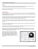
Page 77: ...right Notice that you can set the size of the texture on the bottom left Like with Image Props this option can be very useful For example if you have a backdrop and you want the backdrop to be 50 15...

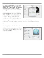
Page 78: ...3D world in the next section Diffuse and Specular light are compliments Diffuse is the reflection of light off of an uneven surface Specular is the mirror like quality of reflection off of a smooth su...

Page 79: ...ese options Use the Textured Brick Color and Brick Bump I set the Bump 1 Amplitude I made my colors a bit darker We ll use this in our scene later Renderworks obviously comes with many shaders and man...

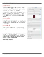
Page 80: ...ow that you have some textures let s add them to some classes Open the Class Tab in the Organization Dialogue You must have Use at Creation checked and Use Textures at Creation Checked You will see th...

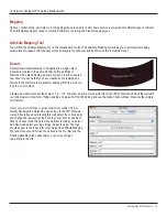
Page 81: ...ave created and is residing as a Texture in the RB Decals are great for adding graffiti to a wall or a logo to a set or carpet Create a new document set the scale to 1 4 1 0 and draw a simple curved w...

Page 82: ...ly doesn t look right Go to View Unified View To se all of the visible layers from the same perspective as the camera Now click Fit to Objects in the View bar you have a nice full screen image Use the...

Page 83: ...orks Adjust and Render some more Remember Textures in the 3D World do not always work as you might expect The virtual world is different Notice that a Texture with a constant Reflectivity will work as...

Page 84: ...jewel logo was created by using the NURBS Extract Edge Tool and applying a texture with Constant Reflection The Illuminated signs are also a simple white texture with Constant Reflectivity An animati...

Page 85: ...ight that placeholder is removed And while this section is short it is deceptively complex Mastering lighting takes time View Menu Options Let s take a look at View Lighting You will see two options S...

Page 86: ...the current view Set View to Light sets the orientation of the current view to the light You ll note that I have turned on Display Light Objects in all views using the Display Tab of the Application P...

Page 87: ...nd look at the fixture with different sources possibly tungsten or CFL before manufacturing You will find a library of custom lamps including glass enclosures in the Libraries Line Lights and Area Lig...

Page 88: ...ou can optimally illuminate your objects Be sure to add a floor and possibly some walls using either extruded primitives or the Floor Command and Wall Tools so you have some surface to cast shadows on...

Page 89: ...e create Viewports to present the drawings you will Make a Top Plan Viewport of the Plot Layer with other appropriate layers visible Cut Section Viewports of the Model Layer using View Unified View an...

Page 90: ...ould be isolated by class and viewed individually for construction When Viewporting scenic elements I create one viewport on a sheet and then duplicate the viewport by either alt option and dragging o...

Page 91: ...hould look like the one here Note the thicker grey border that identifies that you are on a sheet layer Key to Instrumentation Right click on the viewport and select Edit Annotations from the contextu...

Page 92: ...yer is a very common mistake Remember that the sheet layer is 1 1 scale so if you dimension on the sheet layer the Dimension Tools measure the distance on the page In 1 2 scale instruments on 18 457m...

Page 93: ...g box This allows you to customize each sheet and each set of drawings Once you have entered the title block data duplicate the sheet layer by right clicking on the sheet layer in the Sheet Layer tab...

Page 94: ...ke a class for my Drawing Labels so I can color them and give them a heavy line weight I like the drawing labels to anchor my drawings Remember the design of your documents is a critical part of your...

Page 95: ...ably not going to have a sheet of paper 16 long to show the mouldings but you can have several copies of the same viewport with just the different mouldings visible I could go on Any 2D shape can be a...

Page 96: ...ource Browser Double click on the schedule in the Resource Browser to add it to the drawing and then you can double click on the schedule in the drawing to edit it If you are a Lightwright user Vector...

Page 97: ...not solids they are defined pure geometric planes in 3D space They have no defined thickness NURBS objects uniquely combine ease of drawing and precision You will find NURBS Tools in the 3D Modeling...

Page 98: ...avorite methods or techniques I have found most useful Fillet or Chamfer Edge These tools work just like the 2D Fillet and Chamfer that we have already used Except these tools allow you to fillet or c...

Page 99: ...three options Extrude Face Mode Move Face Mode Extrude Curve Mode Each of these can be modified by the and buttons The Plus extends the object with a protrusion the minus creates a cutout by cutting i...

Page 100: ...ed Guide Extrude Curve mode allows you draw a NURBS Curve shape or NURBS Circle on a face and protrude or cut with the new shape The distance of the protrusion or cutout can also be specified by enter...

Page 101: ...t 0 0 in Top Plan Modify Convert Convert to NURBS Go to the Front View Duplicate one copy 4 101 6mm on the Z Axis Go Back to the Top Plan and create a 2 50 8mm square at 0 0 Convert to NURBS Change th...

Page 102: ...guided by a rail curve on a plane perpendicular to the plane containing the profile curve and axis To create a NURBS surface with profile and rail 1 Create an axis rail and profile out of NURBS curve...

Page 103: ...me of those possibilities You can clearly see there is much more to explore The same is true of everything we have covered Your journey towards proficiency in Vectorworks should be rewarding and excit...

Page 104: ...addonsAW html Vectorbits http VECTORBITS COM VectorBits home html Vector Depot http www vectordepot com Landru Design Vectorworks plug ins http www landrudesign com DefaultFrameSet htm index htm Landr...

Page 105: ...an EMMY Award winning scenic designer who works in theatre film television and corporate environments including themed architecture corporate and museum exhibits special events and specialty graphics...

Page 106: ...torworks net T 410 290 5114 F 410 290 8050 2009 Nemetschek North America Inc Vectorworks is a registered trademark of Nemetschek North America Inc Renderworks is a trademark of Nemetschek North Americ...

Reviews: