background image

11

Installation and connection guidance

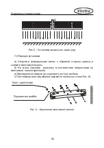
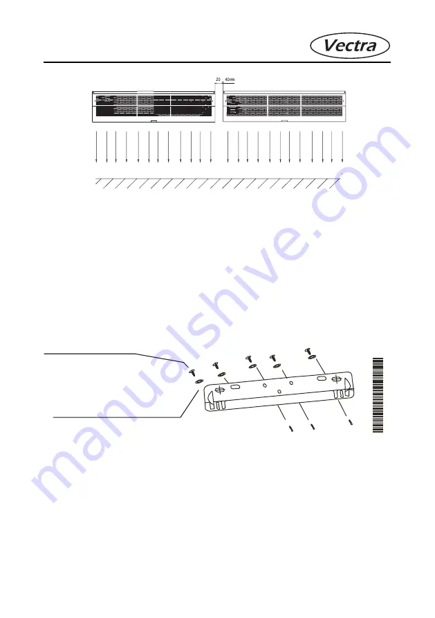
Figure 5. Abreast installation of several Air Curtains. 

7.2 Please follow the next steps at Air Curtain installation. 

a) Unscrew the screws and remove the mounting plate 
b) Make the marks on the wall according to mounting plate holes.
c) Drill the holes and put the dowels into the wall.
d) Fix the mounting plate on the wall using the screws.
e) Install Air Curtain on the mounting plate. A interval must be more than

100 mm (Fig.6)

Figure 6.  Mounting plate fixing.

Screw

Spring nut

Summary of Contents for FM-1309-Z

Page 1: ...USER S MANUAL AIR CURTAINS Models FM 1309 Z Y FM 1312 Z Y FM 1315 Z Y...

Page 2: ......

Page 3: ...ION 5 3 TECHNICAL PARAMETERS 6 4 ASSEMBLY AND OPERATION PRINCIPLE 7 5 OPERATION MODES AND CONTROL OF AIR CURTAIN 7 6 AIR CURTAIN MAINTENANCE 9 7 INSTALLATION AND CONNECTION GUIDANCE 9 8 SERVICE 15 16...

Page 4: ...4 Constructive features Length of Air Curtain x 10 cm Wind wheel impeller diameter cm Air Curtain code Constructive features Y infrared remote controlling Z axial type Legend FM 13 XX Z Y...

Page 5: ...height is 2 5 m 2 CAUTION 2 1 Please follow the general rules of electrical safety at electrical instru ment operation 2 2 The unit doesn t be installed near highly inflammable materials Don t allow t...

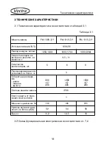
Page 6: ...Z Y Power Supply V Hz 230 50 Air volume m3 h 1050 1400 1680 1760 1680 2240 Air speed at output grate more than m s 8 5 11 Number of wind wheels pieces 5 6 8 Recommended installa tion height less than...

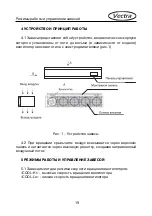
Page 7: ...ding on Model Figure 1 Air Curtain assembly 4 2 At wind wheel impellers an air is rejected throw the upper panel and discharged throw the outlet grate creating the direct air flow 5 OPERATION MODES AN...

Page 8: ...urtain is controlled by infrared remote control or ON OFF key on the front panel of Air Curtain Fig 2 and 3 Figure 2 Infrared remote control Figure 3 Air Curtain control panel ON OFF Key High speed in...

Page 9: ...is from 40 C to 40 C 6 2 Relative humidity is less than 80 at 20 C 6 3 Dust and other air dirt contents are less than 10 mg m3 7 INSTALLATION AND CONNECTION GUIDANCE 7 1 Installation requirements 7 1...

Page 10: ...n must be installed on a stable and strong wall able to keep it weight 7 1 5 Recommended installation height it less than 2 3 m 7 1 6 When the entrance is wider than the unit it is recommended to inst...

Page 11: ...a Unscrew the screws and remove the mounting plate b Make the marks on the wall according to mounting plate holes c Drill the holes and put the dowels into the wall d Fix the mounting plate on the wa...

Page 12: ...interval must be more than 100 mm Figure 7 Air Curtain Installation on the mounting plate g Adjust the installation angle respectively a door if it is necessary Installation angle is adjusted by speci...

Page 13: ...qualified specialist accord ing to regulations 7 3 2 Power cable must be connected to the terminal board 7 3 3 Connection to the charging line must be executed by the all polarity switch with the mac...

Page 14: ...r key control air curtains is according to Fig 10 Fig 10 Electric circuit for key control air curtains 7 4 2 Electric circuit for infrared remote control air curtains is according to Fig 11 Fig 11 Ele...

Page 15: ...C and relative humidity 80 at 20 C excluding kicks beats and movements inside a transport 8 2 Air Curtains must store in manufacturer s packing at 40 C to 50 C and average monthly humidity 80 at 20 C...

Page 16: ...Y Z 16 FM 13 XX Z Y x10...

Page 17: ...1 3 2 2 1 2 2 2 3 2 4 2 5 2 6 17...

Page 18: ...18 FM 1309 Z Y FM 1312 Z Y FM 1315 Z Y 230 50 3 1050 1400 1680 1760 1680 2240 8 5 11 5 6 8 3 900 157 220 1200 157 220 1500 157 220 IP20 1 130 160 215 52 54 58 11 2 14 5 18 3 3 1 3 1 3 1 3 2 7 4...

Page 19: ...4 4 1 1 1 4 2 5 5 1 COOL Hi COOL Lo 19...

Page 20: ...5 2 5 2 1 ON OFF 2 3 2 3 20...

Page 21: ...5 2 2 ON OFF COOL Hi Hi ON OFF COOL Lo Lo 5 2 3 ON OFF 6 6 1 40 40 6 2 20 80 6 3 10 3 7 7 1 7 1 1 100 7 1 2 10 21 COOL Hi COOL Lo OFF...

Page 22: ...7 1 3 4 7 1 4 7 1 5 3 7 1 6 20 40 22 A B FM 1309 Z Y 900 750 FM 1312 Z Y 1200 1050 FM 1315 Z Y 1500 1350 4...

Page 23: ...5 7 2 6 6 23...

Page 24: ...7 7 0 10 8 8 24 100...

Page 25: ...7 3 7 3 1 7 3 2 7 3 3 3 3 1 5 2 25...

Page 26: ...7 4 7 4 1 10 10 7 4 2 11 11 26...

Page 27: ...27 8 8 1 t 40 50 80 20 8 2 40 50 80 20 2...

Page 28: ...VECTRA ELECTRICAL CO LIMITED 29 HARLEY STREET LONDON United Kingdom...

Reviews: