16.
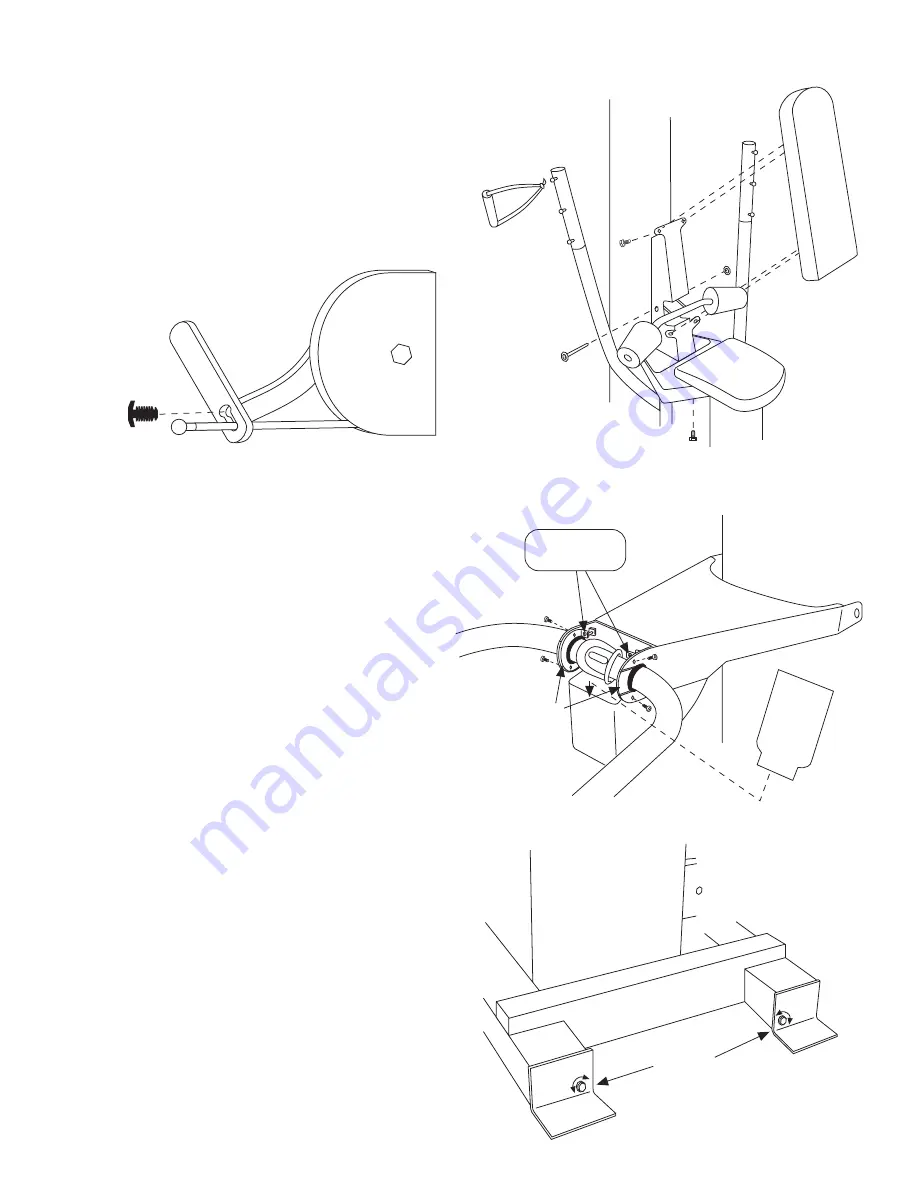
Connect cables to cross chest fly cams. Use plastic hole-plugs in keyholes
to prevent disconnection.
FIG. 10A.
17.
Install seat bottom (R) (1/4-20 x 3/4 hex screws, qty. 2). Note: If you are
installing a leg/calf press option, there are seat handles which install under
seat bottom (R). See instructions with the leg/calf press option for details. Install
the lat hold down (S) with the lever on the right pointing up. Line up the 1/2"
holes and insert the pivot (1/2" diameter rod and shaft retainers). Install shaft
retainer with a hammer. Install seat back (T) (1/4-20 x 3/4 hex screws, qty. 4).
Install one single handle per side (U).
FIG. 10.
FIG. 10
R
S
T
U
Assembly Instructions
(cont.)
FIG. 10A
LEFT CAM
DETAIL
18.
Now install press handle (V). Insert the press handle (V) into the front
of the press arm lever (I) such that the pin engages one of the notches inside
with a bracket from the press handle on each side. A nylon bushing should
be positioned (slot toward weight stack) to engage each side of the press
arm lever (I). Secure each bushing with a bushing cap (W), bent flanges up.
Install the screws in the sides (1/4-20 x 1/2 pan head phillips, qty. 4) and the
tensioning screws (1/4-20 x 1-1/4 oval head, qty. 2). Tighten the 4 side screws
finger tight. Now tighten the tensioning screws until the slop is taken up.
Do not overtighten. Once the slop is removed from the pivot, but the joint
still rotates easily, tighten the 4 cross screws. Check the adjustment
lever's operation at this point. When the lever is operated in either
direction, the pin should retract fully, allow the press handle to rotate.
When the lever is released, the pin should lock the press handle by
snapping all the way into the next notch. Adjust if necessary. When correctly
adjusted, the latch pin will be forced by the spring all the way against the far
end of the slot it travels in. The adjustment lever will pull it almost, but not
all the way, to the other end of the slot.
It is very important
that it be
adjusted such that it goes all the way to the end of the slot with the pressure
of the spring. Now install the plastic cover (X). With the textured side out,
insert the narrow end down into the front of the press arm lever (I). Curve it
back and insert the end with the hole under the top of the press arm lever (I).
The hole snaps onto a hook inside to secure it.
FIG. 11.
19.
Next adjust the position of the stack column. First make sure all
frame bolts
are very tight. Behind the stack, near the floor on each leg of the
main frame (B) you will find a bolt head. Turning either bolt head (9/16"
wrench) will move the bottom of that side of the stack column (F). Clockwise
moves the bottom of the stack back, counter-clockwise forward. Make sure
the "Mode Selection Knob" near the top of the main column (C) is in "Free
Mode." The wheels on the bottom of the press arm lever (I) will be in the "V"
of the saddle of the press arm support (A). First adjust the bottom of the stack
column to center the wheels on the press arm support (A). Once this is
accomplished, check the alignment of the "Mode Selection Knob." If it slides
into "Fixed Mode" easily, go to the next step. If it hits one side of the hole
first, more adjustment is necessary. To bring the top of the stack column (F)
toward the press station, the bottom of the stack needs to go away. Turn the
two bolt heads clockwise. Turn them an equal number of turns to keep the
press arm centered on the press arm support (A). To move the top of the stack
column back, turn the bolt heads counterclockwise.
FIG. 12.
W
TENSIONING
SCREWS
I
V
X
FIG. 11
Stack
Column
Position
Adjustment
F
B
FIG. 12


