VECTRONIC Aerospace
Doc. No.:
TT5 User’s Manual
Date:
05.06.2020
This design is the property of VECTRONIC Aerospace GmbH. Unauthorized duplication or distribution to a third party is prohibited.
5 /10
1
The Transmitter
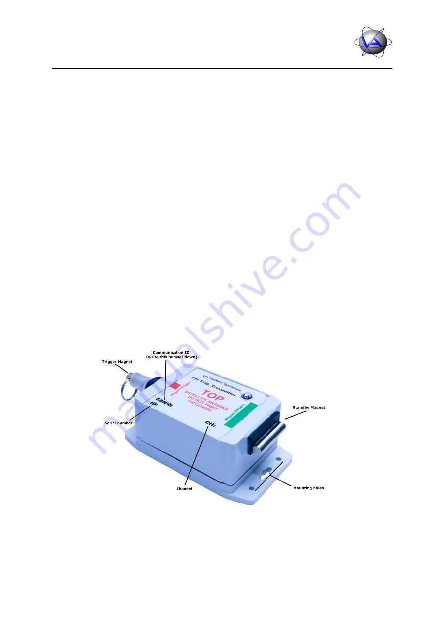
The Trap Transmitter TT5 is a small grey box as shown in Figure 1. The top side is labelled
“TOP” and must not be covered or painted since this would obstruct satellite communication.
In the corners you find several mounting holes to attach the TT5 to a mounting structure.
Make sure that the TOP-side points away from the mounting structure and towards the
sky.
The sticker on the gives you information about the ‘ESN’, ID and ‘CH’. ESN is the
communication ID of the transmitter. Write down this number as this will help you identify
the transmitter once you receive status or alarm messages. The ID is the serial number of the
TT5 and can also be used to identify the transmitter. CH is the transmission channel of the
Globalstar transmitter. Transmission channel is either A (North America) or C (rest of the
world).
On one side there is a patch of hook-and-loop tape. Here you can attach the standby magnet
which is used to switch the transmitter ON (Normal Mode, magnet is removed) or OFF
(Stand-By Mode, magnet is attached).
The trigger magnet is located opposite of the standby magnet. This magnet is the connection
between trap and trap transmitter.
Figure 1: TT5 Trap Transmitter in Stand-by mode


