background image

VEC-121K Owner's Manual 

Crystal Radio Set Kit 

26 

3.  Connect a good ground connection to the crystal receiver.  Use the 7 foot 

length of stranded hookup wire supplied with the kit to make the ground 
connection between a good earth ground and the Fahnstock clip on the 
receiver. 

4.  Connect a long wire antenna to the Fahnstock clip on the receiver. 

5.  Carefully tune the tuning knob while listening for signals in the earphone.  

You should be able to copy at least one, and maybe several, stations without 
difficulty. 

What can I hear?  

You should be able to hear local stations without much 

difficulty.  The crystal set tunes the entire broadcast band from 530 kHz to 1700 
kHz.  The antenna and ground system are the keys to success when using crystal 
sets.  Where you live affects how well you receive signals.  If you live in a salt 
marsh, or along the shore, you may experience exceptional reception.  The 
fellow living in an arid area with poor soil moisture may have much poorer 
reception. 

When to listen?  

You should hear local stations at any time of the day.  At dusk, 

radio signals propagate over greater distances.  Listening just before the sun goes 
down may yield some pleasant surprises!  Also, as the seasons change, you may 
find you can hear different distant stations at sundown.  Keep a simple log of 
new stations when you receive them.  Note the time, call letters and frequency.  
It’s always fun to add a “new one” to the list. 

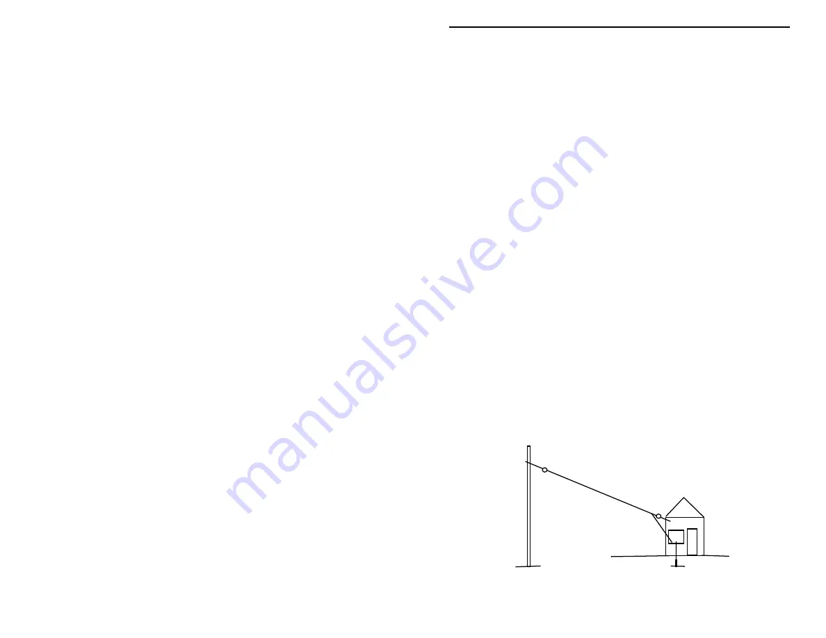
Erecting a good antenna 

Your radio will work only as good as the antenna and ground it is connected to 
do.  The best antenna for a crystal set is located outdoors, it is between 100 and 
30 feet long, and is mounted high and in the clear.  Your kit includes enough 
wire to make an outdoor 40 foot wire antenna and short lead-in wire to the 
crystal set receiver. 


Summary of Contents for VEC-121K

Page 1: ...ific part is no longer available or if Engineering has determined that an alternative component is more suitable Vectronics reserves the right to make substitutions at any time In most cases these cha...

Page 2: ...it well and include the minimum payment plus shipping and handling charges 25 00 total No work can be performed without pre payment Also provide a valid UPS return address and a day time phone number...

Page 3: ...ximum signal to the set TOOLS AND SUPPLIES Having the right tool to do a job always makes things go better There is no soldering required and only a few basic hand tools are needed to assemble your VE...

Page 4: ...o assemble plastic model airplanes are safer to work with and may also be used instead of super glue However they will require a longer time to dry Always have an adult advise and supervise your use o...

Page 5: ...few days This will allow the stain to fully cure or dry so it does not interfere with the tape adhesive BEFORE YOU START BUILDING Your work area Use a good workbench with good lighting so you can see...

Page 6: ...a SlinkyTM toy Doing so will cause the wire to twist and make kinks when you try to use it Instead hold the spool of wire in both hands and carefully unroll the wire from the spool Re tape the unused...

Page 7: ...the Fahnstock clips mounted on the pine board Note we show the wire as a dotted line where it passes under the Fahnstock clip When the Phillips screw is tightened a good electrical connection is made...

Page 8: ...t 6 The wire insulation is removed where shown in the directions and made into a half loop as shown above The above drawing shows a through connection being made to a Fahnstock clip The dotted line sh...

Page 9: ...the Vectronics kit warranty section of the manual Qty Part Description 8 Phillips head screws 1 5 inch length of white 2 1 2 diameter PVC plastic pipe 1 100 foot spool of 18 AWG enamel coated wire 6...

Page 10: ...VEC 121K Owner s Manual Crystal Radio Set Kit 8 Resistor Germanium diode 1N34A STEP BY STEP CONSTRUCTION...

Page 11: ...small hammer make a small punch mark at each of the eight screw hole locations These marks will show you where the screw holes are located on the board Don t drive the nail into wood We need only make...

Page 12: ...holes align properly with the breadboard s mounting holes you may remove the coil and return the screws to the parts bag If things don t match up just right you will have to mark the correct position...

Page 13: ...If the copper wire kinks during handling smooth it out as best you can before trying to wind it We are going to wind a single layer coil this is called a solenoid winding The winding is done in sever...

Page 14: ...tight even and spaced together After several turns are completed examine your work Keep your thumb in place so the wire doesn t loosen on the coil form The wire windings should be even and spaced so t...

Page 15: ...s you have just completed Are they tightly wound and free of gaps between adjacent windings Squeeze the newer windings towards the starting windings to close up any gaps When you re satisfied use mask...

Page 16: ...six Fahnstock clips and six of the eight Phillips screws supplied with the kit Refer to the positioning guide below for the following steps GND ANT EAR2 DET1 DET2 EAR1 In the following several steps...

Page 17: ...the remaining two Phillips head screws Mount the coil to the board using the two Phillips head mounting screws Before tightening the screws make sure the two 16 coil lead wires are oriented towards th...

Page 18: ...clip Route the through connection loop so it passes between the ANT Fahnstock clip and breadboard Tighten the ANT clip mounting screw so it is snug Measure and mark the wire lead emerging from the ant...

Page 19: ...ntil snug Measure the wire exiting from the EAR2 connection and at the 5 5 point remove 1 of insulation from the wire Form the area of wire stripped of insulation into a second through connection half...

Page 20: ...in the kit Remove 1 of insulation from each end Form each end of the wire into an end connection Loosen the screws mounting the Fahnstock clips DET2 and EAR1 Take one of the wire end connections and...

Page 21: ...en the two Phillips screws for EAR1 and EAR2 clips Put one of the half loop connections between the top of the clip body and the bottom of the screw head for the EAR1 clip Adjust the size of the loop...

Page 22: ...ery small diameter and may not be held tightly enough by the clip unless the leads are made a bit thicker Follow the diagram below and clip the diode s anode lead into the DET1 Fahnstock clip and the...

Page 23: ...es As the shaft is turned the plates are either meshed or unmeshed changing the capacitance value This is how the tuning capacitor works The tuning capacitor will be mounted at the front center of the...

Page 24: ...y opening in the plastic capacitor housing Take the wire from the GND clip and insert it into this capacitor opening Carefully feed the wire so it passes through the capacitor body it will be between...

Page 25: ...to a length of 4 Remove 1 of insulation from the wire end Wind the wire over the stud to form three tightly wound turns See the following drawing Use enough wire so when finished you have a small pig...

Page 26: ...citor body outline by tracing its outline onto the breadboard with a pencil Find the double sided foam tape Remove one of the protective covers from one side of the tape Place the sticky side over the...

Page 27: ...uning knob on the shaft extension This completes the construction of the VEC 121K crystal set receiver TESTING AND ALIGNMENT 1 Turn the capacitor shaft in a counter clockwise direction until the stop...

Page 28: ...ceive signals If you live in a salt marsh or along the shore you may experience exceptional reception The fellow living in an arid area with poor soil moisture may have much poorer reception When to l...

Page 29: ...is being used The most effective ground is a 10 foot ground rod driven into the earth If you have a TV antenna on your home it should be connected to a ground rod for lightning protection If it is ne...

Page 30: ...s to the tuning capacitor were used Signals are very weak or I can only hear one station Again this may be normal if there are no strong signals in your area Check your ground and antenna connections...

Page 31: ......

Reviews: