5-4
Multiple Scan Operation
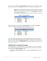
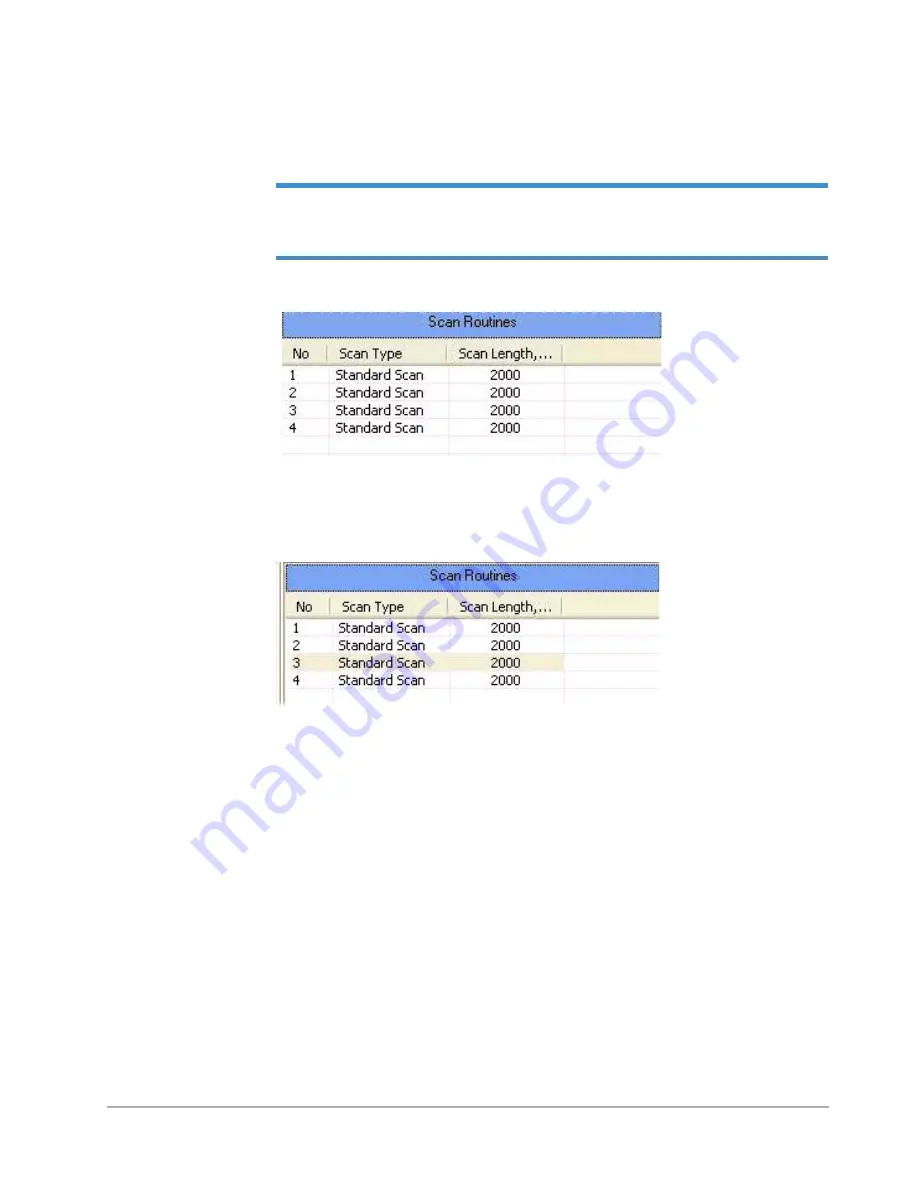
The scan routine is identified in the
Scan Routines
area by three entries: the left number is the scan
number; the center entry is the
Scan Type
and the number to the right is the scan length (see
NOTE –
After you have defined the X location and Y location according to the instructions
Defining Scan Location and Length on page 5-4
the
Scan Routines
area also shows
the X location and Y location
in µm .
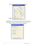
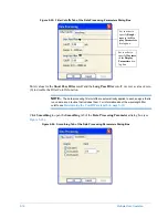
Figure 5-3: Scan Routines Area
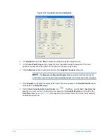
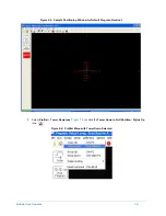
Double-click any one of the scans listed in the
Scan Routines
area to open the
Scan Routines
window, which displays the parameters for that scan routine (see
Figure 5-4: Scan Routines Area with Scan Routine Selected
At this point, all four scan routines in your current automation program have the same values. You
can use the functions described in the next section to determine new values for the location and
length of each scan routine in the
Sample Positioning
window. Furthermore, you can adjust or edit
values for each scan routine in the
Scan Routines
window, using the functions described in
.
Defining Scan Location and Length
This procedure determines the appropriate scan starting location and scan length for measuring the
vertical standard that came with your system or another sample. You define the scan location and
scan length from the
Sample Positioning
window.
1
Select
Window
>
Sample Positioning
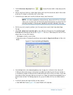
from the menu to display the
Sample Positioning
window (see
Summary of Contents for Dektak 150
Page 1: ......
Page 7: ......
Page 17: ......
Page 81: ......
Page 105: ......
Page 149: ......
Page 191: ......
Page 251: ......
Page 257: ...A 6 Facilities Specifications Figure A 6 Dektak 150 without Enclosure Side View ...
Page 258: ...Facilities Specifications A 7 Figure A 7 Dektak 150 Dimensions without Enclosure Top View ...
Page 259: ...A 8 Facilities Specifications Figure A 8 Dektak 150 without Enclosure Center of Mass ...
Page 273: ......
Page 283: ......
Page 321: ......
Page 331: ......
Page 333: ......
Page 336: ......
Page 337: ......
Page 349: ......

