Calibration and Maintenance
9-19
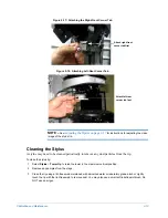
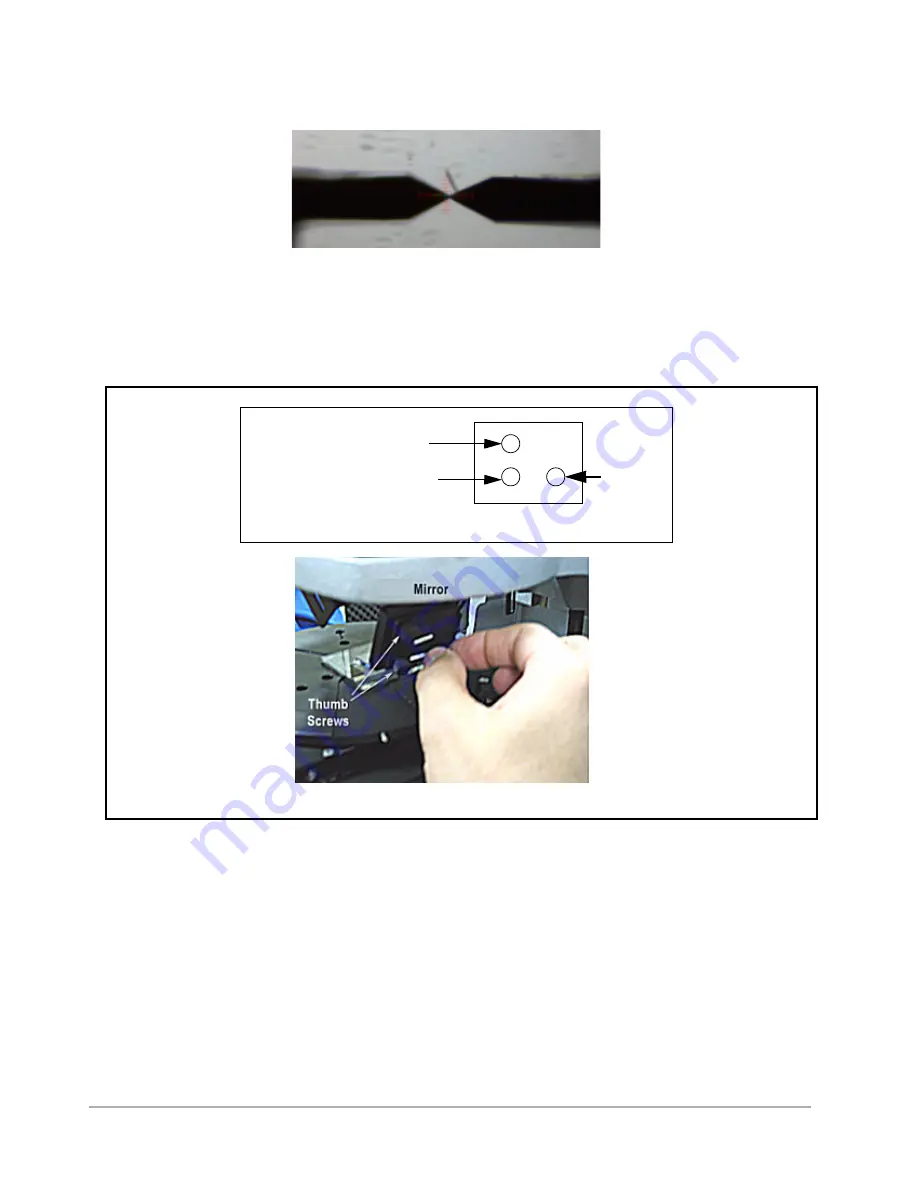
Figure 9-25: Stylus Tip in Focus
4
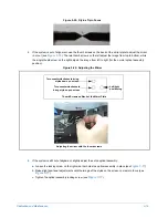
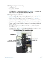
If the system is out of alignment, use the thumb screws on the back of the mirror plate to adjust the mirror
in or out (see
). The two thumb screws on the left adjust the image from top to bottom, while
the single thumb screw on the right adjusts the image from left to right (for the normal optical assembly
position).
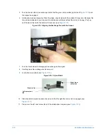
Figure 9-26: Adjusting the Mirror
5
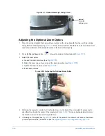
If the system is still out of alignment, slightly adjust the entire optical assembly:
a.
Loosen the locking screw on the right side that holds the optical assembly in place (see
b.
Make slight positional adjustments until the image of the stylus on the screen comes into focus (see
c.
Tighten the optical assembly locking screw (see
).
Adjusting the mirror with the thumb screws
Thumb Screws on Back of the Mirror Plate
Turn counterclockwise to bring
stylus down on screen
Turn counterclockwise to
bring stylus up on screen
Left/right
positioning
Summary of Contents for Dektak 150
Page 1: ......
Page 7: ......
Page 17: ......
Page 81: ......
Page 105: ......
Page 149: ......
Page 191: ......
Page 251: ......
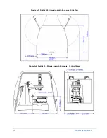
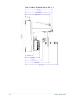
Page 257: ...A 6 Facilities Specifications Figure A 6 Dektak 150 without Enclosure Side View ...
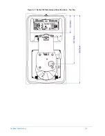
Page 258: ...Facilities Specifications A 7 Figure A 7 Dektak 150 Dimensions without Enclosure Top View ...
Page 259: ...A 8 Facilities Specifications Figure A 8 Dektak 150 without Enclosure Center of Mass ...
Page 273: ......
Page 283: ......
Page 321: ......
Page 331: ......
Page 333: ......
Page 336: ......
Page 337: ......
Page 349: ......

