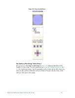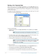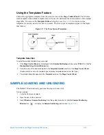
background image

Basic User Interface and Stage Positioning Techniques

3-15

6

Position the sample in the center of the stage below the stylus. 

IMPORTANT! 

if you are using the vertical standard that came with your system, position 

it according to the instructions in the next section.

7

If the Z-axis limit switch has been modified, you may need to adjust it. The Dektak 150 has four inches of 
clearance. 

Positioning the Vertical Standard

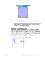
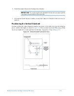
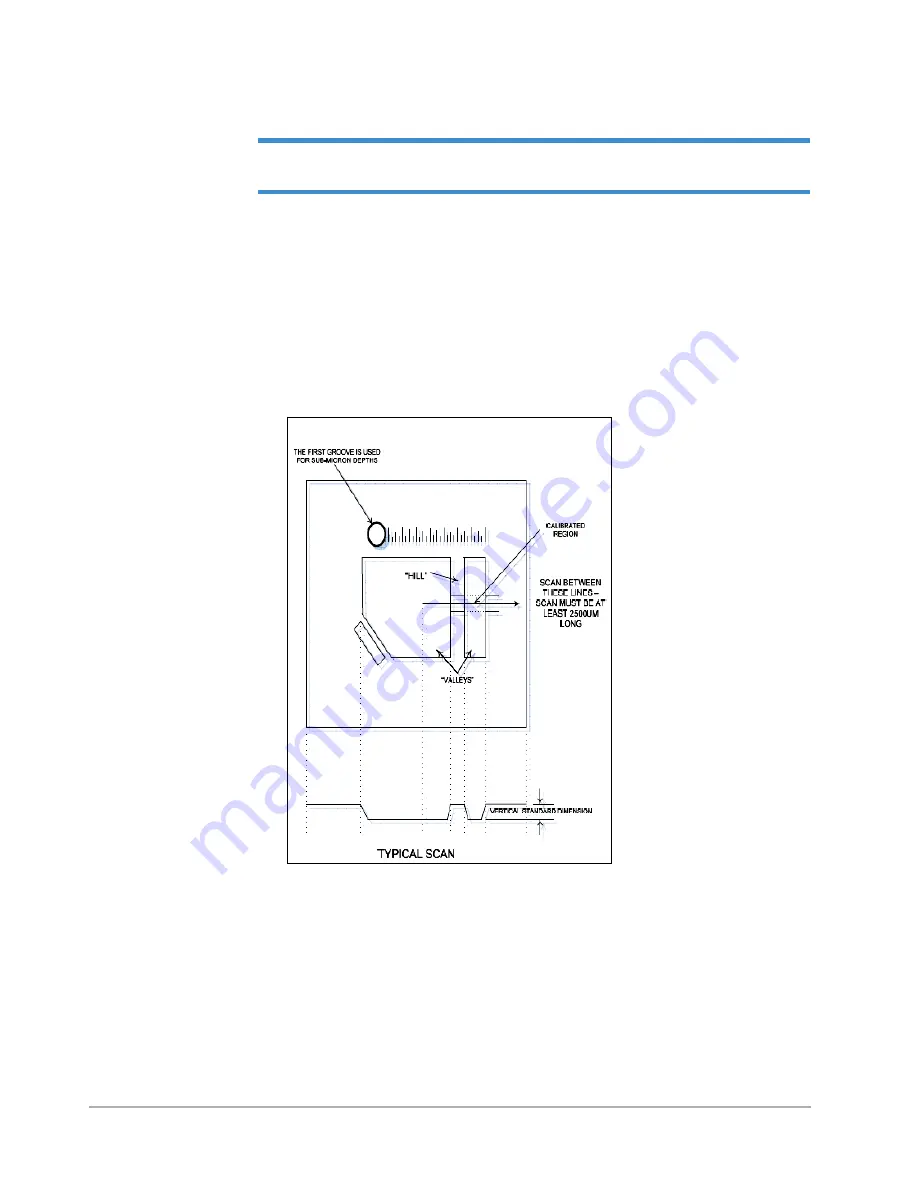
You must position the vertical standard so that the scan travels over the hill, down into the calibration 
groove, and then back again, as shown in 

Figure 3-14

. The scan must be at least 2500 

µm long. 

When 

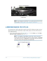
the vertical standard is correctly positioned on the stage, it appears as it does in 

Figure 3-15

.

Figure 3-14:  Vertical Standard Positioned for Scan

Summary of Contents for Dektak 150

Page 1: ......

Page 2: ...P N 980 294 Standard P N 980 298 Cleanroom Revision A DEKTAK 150 SURFACE PROFILER USER S MANUAL ...

Page 3: ...ld given or loaned to another person Under the law copying includes translating into another language or format Veeco Instruments Inc retains all rights not otherwise expressly granted here Nothing in this notice constitutes a waiver of our rights under U S Copyright laws or any other federal or state law TRADEMARK NOTICE Wyko and Vision are registered trademarks of WYKO Corporation and Veeco Inst...

Page 4: ...tware These services will be performed at Seller s option at either Seller s facility or Buyer s business location For repairs performed at Seller s facility Buyer must contact Seller in advance for authorization to return equipment and must follow Seller s shipping instructions Freight charges and shipments to Seller are Buyer s responsibility Seller will return the equipment to Buyer at Seller s...

Page 5: ...uipment may be impaired Notices The information in this document is subject to change without notice No Liability is assumed for errors contained herein or of incidental or consequential damages in connection with the furnishing performance or use of the material Document Conventions GENERAL CONVENTIONS Your system hardware operates with the the Dektak 150 software and Wyko Vision software under M...

Page 6: ... locate and identify information boldface Menu titles commands icons and check box and button names are shown in boldface type italic type Italic type indicates new terms title and heading references and shows emphasis monospace type Code examples and commands that you must type in exactly as they appear are shown in monospaced type SMALL CAPITALS Hardware placards and keyboard key labels are show...

Page 7: ......

Page 8: ...Two Axis Manual Stage 1 6 X Y Auto Stage and Single Axis Y Auto Stage 1 6 Scanning 1 6 Profile Manipulation and Measurement 1 6 Measurement Output 1 7 Dektak 150 Software Functions 1 7 Automation Programs 1 7 Scan Routines 1 7 Analytical Functions 1 7 Data Plot Window 1 8 Dektak 150 Reference Materials 1 9 Context Sensitive Help 1 9 Online Help 1 9 This Manual in PDF Format 1 9 How to Use This Man...

Page 9: ...stalling a Printer 2 29 Establishing a Network Connection 2 29 Changing the Voltage Setting 2 29 Chapter 3 Basic User Interface and Stage Positioning Techniques 3 1 Start Sequence 3 1 Power On 3 1 Software Interface and Stage Controls 3 3 Stage Control 3 3 Manual X Y Stage 3 3 X Y Auto Stage and Y Auto Stage 3 3 Microsoft Windows XP 3 3 Mouse Functions 3 4 Keyboard Shortcuts 3 4 Assigning Analytic...

Page 10: ... Setting the Zero Point 4 15 Making a Delta Average Step Height Measurement 4 15 Changing the Plot Magnification 4 17 Saving the Data Plot 4 18 Printing the Scan Data 4 20 Saving an Automation Program 4 20 Aborting an Operation 4 22 Opening a Dektak 150 Scan in Vision 4 23 Saving upon Exiting the Dektak Program 4 24 Chapter 5 Multiple Scan Operation 5 1 Loading the Sample 5 1 About the Automation ...

Page 11: ...3 Chapter 6 Analytical Functions 6 1 About Analytical Functions 6 1 Roughness Parameters 6 2 Waviness Parameters 6 6 Height Parameters 6 7 Geometry Parameters 6 7 Running a Scan and Leveling the Trace 6 8 Making an Average Roughness Measurement 6 9 Determining the Cutoff Wavelength 6 10 Short High Pass Filter 6 11 Long Low Pass Filters 6 11 Band Pass Filter 6 11 Activating the Cutoff Filters 6 11 ...

Page 12: ...Positions from the Data Plot Window 7 17 Display Range 7 18 Display Data Type 7 18 Data Processing Parameters 7 19 Filter Cutoffs 7 19 Smoothing 7 20 Step Detection 7 21 Chapter 8 Menu and Toolbar Descriptions 8 1 Startup Window 8 1 Default Menu Bar 8 2 Additional Menus 8 2 Toolbar 8 2 Status Bar 8 2 File Menu 8 2 Run Menu 8 4 Profiler Menu 8 5 Setup Menu 8 7 User Interface Settings 8 8 Directorie...

Page 13: ...1 Sample Positioning Window Toolbar and Icons 8 32 Data Plot Window Toolbar and Icons 8 34 Dektak Database Toolbar and Icons 8 35 Chapter 9 Calibration and Maintenance 9 1 Overview of Vertical Calibration 9 1 Calibrating the 65 kÅ Range 9 2 Making the Preliminary Measurements 9 2 Calculating the Average Step Height 9 4 Setting the Vertical Calibration 9 5 Calibrating the Other Ranges 9 6 Calibrati...

Page 14: ... Entering Stress Parameters C 5 Stress Results C 5 Constraints and Limitations C 6 Appendix D Step Detection Function D 1 Step Detection Method D 1 Step Detection Parameters D 1 General Settings Tab D 2 Detection Method Section D 2 Detection Range Section D 3 Automatic Leveling D 3 Save Changes To Scan Routine D 3 Enable Step Detection D 3 Every Step Tab D 4 Step Description Section D 4 Analytical...

Page 15: ...g Vision s Basic Functions E 8 Start Up Window E 8 Open E 9 Save E 10 Printing E 10 Vision Toolbar E 10 Analyzing Data E 12 Datasets E 12 Processed Options E 12 Terms Removal Options E 12 Filtering Options E 14 Masking Options E 15 Dektak Options E 16 Displaying Data E 19 Setting the Units E 19 Standard Display File E 19 Display Files for Each Analysis E 19 Display Custom Files cdf E 20 Selecting ...

Page 16: ...rement E 35 Applying a Saved Mask to an Existing Dataset E 36 Saving a Mask to a Configuration File E 36 Datasets and Databases E 36 Appendix F N Lite Option F 1 About the N Lite Option F 1 Main Functions F 2 Servoed Engage F 2 Fine Positioning F 2 Stylus Retouch F 2 Solving N Lite Measurement Problems F 2 Solving Stiction Problems F 3 Appendix G Scan Stitching G 1 About Scan Stitching G 1 Modifyi...

Page 17: ......

Page 18: ...in dimension and up to four inches thick You can use the Dektak 150 to profile surface topography and waviness as well as to measure surface roughness in the nanometer range The system provides a step height repeatability of 0 6 nm 6Å IMPORTANT Environmental data sheets regarding the RoHS compliancy of the Dektak 150 system and the Dell computer that it uses appear in Appendix H of this manual Fig...

Page 19: ... see Figure 1 2 The optional 3 D Mapping and Automation Packages which use either A single axis 4 inch Y auto stage that enables the mapping of 3D images in Wyko Vision see Figure 1 2 A 6 inch X Y auto stage that in addition to 3D mapping provides automation and programmability of up to 200 sites on samples of up to six inches in diameter All three configurations work with the hardware and softwar...

Page 20: ...e optional Dektak 150 monitor provides a 17 inch high resolution flat panel color display It shows programs and graphics in full color along with a color video image of the sample surface from the USB camera in the optical assembly The Dektak 150 software displays the substrate either alone or with superimposed graphics Stylus Surface Profiler The Dektak 150 stylus surface profiler contains all of...

Page 21: ...r With both optical assemblies the intensity illumination adjusts to view samples with differing reflectivity No special video card is required However USB camera drivers must be installed in order for the camera to operate properly Manual X Y Stage The standard stage shown in Figure 1 2 accommodates samples up to four inches thick performs long scans of 55 millimeters and provides 2 inch X Y tran...

Page 22: ...ler takes measurements electromechanically by moving the sample beneath a diamond tipped stylus The high precision stage moves a sample beneath the stylus according to a user programmed scan length speed and stylus force The stylus is mechanically coupled to the core of an LVDT Linear Variable Differential Transformer As the stage moves the sample the stylus rides over the sample surface Surface v...

Page 23: ...Figure 2 1 slows and stops when the sensor is at the null position of the LVDT This procedure guides the Tower Down process each time the stylus makes contact with surface NOTE If your system includes the N Lite or 3 D Mapping option or if the scan is set for Hill or Valley the Tower Down process described above is somewhat different The stage moves the sample as the stylus rides over the surface ...

Page 24: ...tions of the Dektak 150 software Automation Programs Automation Program files can store a number of scan routines on the hard disk Scan routines along with their stage locations and analytical functions are inserted into the automation program Automation Programs are stored for various applications in Windows file format on the hard disk giving the Dektak 150 virtually unlimited program storage ca...

Page 25: ... horizontal distances between the cursor trace intercepts as well as the distances from the vertical and horizontal zero grid lines If you want to change the units of measure before or after the scan you can specify angstroms um or nm If you requested analytical functions the results of those calculations also appear Furthermore the plotting screen includes a Watch List which serves as a real time...

Page 26: ...Dektak 150 application consists of this manual in PDF format To access it follow the instructions in the section below This Manual in PDF Format To access the PDF file of this manual do one of the following On your Windows desktop click the shortcut labled Dektak 150 Manual Select Start All Programs Veeco Dektak 150 Manual pdf Within the Dektak 150 application click Help Contents Dektak 150 Manual...

Page 27: ...iled description of every menu and toolbar in the Dektak 150 user interface while Chapter 9 tells you how to calibrate and maintain your system The first two appendices contain facilities specifications technical specifications and a list of available purchased options The appendices that follow them provide instructions for using specialized functions of the software Whether you actually perform ...

Page 28: ...le 2 1 Safety Symbols Key Symbol Definition This symbol identifies conditions or practices that could result in damage to the equipment or other property and in extreme cases possible personal injury Ce symbole indique des conditions d emploi ou des actions pouvant endommager les équipements ou accessoires et qui dans les cas extrêmes peuvent conduire à des dommages corporels Dieses Symbol beschre...

Page 29: ...CHT Befolgen Sie die gesetzlichen Sicherheitsbestimmungen Ihres Landes Halten Sie nicht authorisierte Personen während des Betriebs fern vom Gerät CAUTION Voltages supplied to and within certain areas of the system are potentially dangerous and can cause injury to personnel Power down everything and unplug from sources of power before doing ANY electrical servicing Veeco personnel only ATTENTION L...

Page 30: ...ofiler Figure 2 2 shows the main components of the back Refer to these figures as you install the system Figure 2 1 Major Components of the Dektak 150 Surface Profiler Camera Optical assembly Manual X Y stage sample positioning stage Scan block Optics mounting plate Base Stylus Sensor Mirror Z axis limit switch rack Tower Camera Mirror ...

Page 31: ...alling the System on page 2 9 Preparing Your Location Prior to unpacking the system you must make sure that your operating environment meets the requirements outlined in Appendix A Facilities Specifications At the minimum you must Ensure that the location is free from excessive air turbulence vibration from machinery dust and dirt or other environmental contaminants IMPORTANT The above factors wil...

Page 32: ...ior to unpacking the Dektak 150 system For more information see Installing the Optional Vibration Isolation Table on page 2 28 Inspecting and Unpacking the Boxes The Dektak 150 ships in multiple boxes Before unpacking any of them check the entire shipment for signs of damage or mishandling Inspect the shock indicator on Box 2 see Figure 2 3 to verify that the system has not been roughly handled Re...

Page 33: ...ported save all boxes and packing materials until acceptance After acceptance save Box 2 to safely ship the profiler should that prove necessary Unpacking the Surface Profiler 1 Move Box 2 as close as possible to the work surface on which the profiler will sit 2 Open the top of the box and remove the top foam and middle foam inserts 3 The system is shipped in a plastic bag Open the top of the bag ...

Page 34: ... facing forward 6 Use the bubble gauge at the base of the tower to verify that the work surface is level see Figure 2 5 Adjust the work surface if necessary Figure 2 5 Verifying that the Work Surface Is Level NOTE The scan block on the base of the system is covered with lint free tissue Leave this tissue in place during installation to protect the precision surface ...

Page 35: ...ocate the red sensor shipping bracket attached to the bottom side of the sensor see Figure 2 7 Loosen the thumb screws and remove the bracket Be sure to keep the bracket for future use Figure 2 7 Removing the Red Sensor Shipping Bracket CAUTION Neglecting to remove any or all of the shipping brackets prior to operation may result in damage to the equipment ATTENTION Oublier d enlever une ou toutes...

Page 36: ...next to the power cord outlet on the back of the computer Figure 2 8 The default setting is 220VAC For instructions on changing the voltage see Changing the Voltage Setting on page 2 29 4 The ground strap is installed on the back of the computer Figure 2 8 Cut the plastic tie that holds the strap in place Figure 2 8 Ground Strap Installed on the Computer 5 Using the Dell instructions located in Bo...

Page 37: ...ing Diagram CAUTION Do not connect or disconnect any cables while the power is on ATTENTION Ne pas connecter ou déconnecter de cables lorsque l appareil est branché VORSICHT Während die Spannungsversorgung eingeschaltet ist dürfen Kabel weder vom Gerät getrennt noch angeschlossen werden ...

Page 38: ...re 2 10 Blank Cable Manifold CAUTION Always use a surge protector the surge protector allows all of the components to power up simultaneously via the single master power switch ATTENTION Toujours utiliser un protecteur de circuit Le protecteur de circuit sert à mettre sous tension tous les éléments du circuit simultanément via le connecteur central VORSICHT Benutzen Sie stets einen Überspannungsbe...

Page 39: ...rial port on the back of the computer Tighten the screws on both ends of the cable see Figure 2 12 Figure 2 12 Connecting the Serial Cable 4 Connect the power supply cable to its port in the cable manifold see Figure 2 10 on the back of the profiler see Figure 2 13 Connecting the USB cable to the profiler Connecting the USB cable to the computer Connecting the serial cable to the profiler Connecti...

Page 40: ... AC cord from the power supply see Figure 2 14 to the power strip Figure 2 14 Connecting the AC Power Cord to the Power Supply 6 Connect the ground strap from the back of the computer to the CASE screw on the back of the profiler see Figure 2 15 Use the 3mm hex wrench to tighten the strap in place ...

Page 41: ...nnect the EMO box to the back of the system and hand tighten the black connector see Figure 2 16 Figure 2 16 Connecting the EMO Box Installing the Optical Assembly 1 Locate the optical assembly in Box 3 2 Loosen the optics hold down screw on the optics mounting plate see Figure 2 17 ...

Page 42: ...t is hand tight see Figure 2 18 Do not overtighten Figure 2 18 ScrewIng the Optical Assembly into the Optics Mounting Plate 4 Rotate the optical assembly slightly such that the camera s USB port faces the rear of the system 5 Tighten the optics hold down screw 6 Connect the USB cable from the system to the camera see Figure 2 19 Keep the optical assembly vertical when screwing it into the optics m...

Page 43: ...debris on the stage or the polished aluminum block follow the cleaning instructions in Cleaning the X Y Stage and Block on page 9 14 1 Locate the X Y stage in Box 3 and remove it from its plastic bag 2 Remove the lint free tissue from the polished aluminum block on the base of the system see Figure 2 20 Figure 2 20 Polished Aluminum Block ...

Page 44: ...he Dektak 150 software will home it upon start up Figure 2 21 Placing the Stage on the Polished Aluminum Block 4 The pinion consists of two parallel gears Figure 2 22 To take up backlash lift the rack mechanism slightly with one hand then turn the outer of the two gears clockwise approximately the distance of at least two of the gear s teeth Figure 2 23 Figure 2 22 Gears of Pinion 5 While holding ...

Page 45: ...so that the green dot see Figure 2 24 is NOT visible that is the magnet is disengaged 3 Open the stylus case and gently remove the stylus Lift the stylus by its central disk not by the beam 4 Place the stylus into the exchange tool such that the round disk is aligned with the silver magnet on the tool The stylus arm must be centered within the long trench see Figure 2 24 The stylus tip should poin...

Page 46: ...il the tool is flush with the bottom of the sensor see Figure 2 25 Figure 2 25 Aligning the Exchange Tool with the Sensor 7 Turn the thumb wheel to disengage the exchange tool s magnet 8 Carefully lower the exchange tool to remove it 9 Locate the stylus shield in Box 3 see Figure 2 26 Figure 2 26 Stylus Shield 10 Place the shield around the sensor head such that the right front corner tab is engag...

Page 47: ...ing on page 9 6 Turning on the Power and Checking Out the System 1 Verify that the power switches on the monitor and profiler EMO box are in the On position 2 Make sure that the switch on the surge protector is turned on 3 The EMO box contains three switches a white On switch a black Off switch and a red Emergency Off switch Release the Emergency Off switch by rotating it clockwise until it pops u...

Page 48: ...lowing you to safely position a sample beneath it 7 Select Calibration Stylus Force from the menu bar to open the Force Calibration dialog box see Figure 2 31 Use the slider in the Force DAC section to increase the DAC Value to maximum Observe and verify the stylus swings to the down position Use the slider to decrease the DAC Value to minimum Observe and verify that the stylus moves to the up pos...

Page 49: ...es sont correctement connectés et non endommagés Vérifier que l interrupteur à l avant de l ordinateur est en position ON Verifier que tous les fils électriques sont branches correctement aux prises de courant Répéter la procédure de démarrage ATTENTION Falls sich das Dektak 150 mit dem beshriebenen Verfahren nicht einschalten lassen sollte überprüfen Sie die folgenden Punkte bevor Sie sich mit Ve...

Page 50: ...rd on the stage beneath the stylus with the printing facing the front of the system see Figure 2 33 The system scans from front to back so be sure there are at least a few millimeters of the standard located to the back of the stylus tip NOTE The above activity cannot damage the stylus sensor However clipped data may appear on the monitor 3 Press the Stylus Down button to lower the stylus onto the...

Page 51: ... the zoom ring until you arrive at the desired position c Tighten the zoom lock screw d If necessary refocus Figure 2 35 Adjusting the Optional Zoom Optics 6 Watching the computer monitor turn the thumb screws on the back of the mirror plate if necessary to align the stylus tip with the center of the crosshairs see Figure 2 36 This is a delicate adjustment so turn the screw in increments of only h...

Page 52: ...ee Figure 2 33 Figure 2 37 Adjustment Knobs on the Stage 2 Click the Scan Here button to perform the factory loaded measurement routine Stylus tip aligned with center of the crosshairs Adjusting the mirror with the thumb screws Thumb screws on the back of the mirror plate Turn counterclockwise to bring stylus down on screen Turn counterclockwise to bring stylus up on screen Left right positioning ...

Page 53: ...face appears over the live video see Figure 2 38 Figure 2 38 The Scan Profile during a Measurement At the end of the measurement the Data Plot window appears see Figure 2 39 Figure 2 39 Typical Data Plot Window 3 When you are ready to replace the vertical standard in its case a Open the case ...

Page 54: ...t down the software The tower raises 2 Press the black Off switch on the EMO box to turn off power to the system Installing the Environmental Enclosure 1 Remove the pre assembled environmental enclosure from Box 4 and place it over the system 2 Slide the cables slide through the rear slot 3 Attach the enclosure s ground strap to the grounding screw on the back of the profiler NOTE The enclosure th...

Page 55: ... your site Review the information in Appendix A Facilities Specifications and then refer to the manufacturer s instructions to install the platform or table INSTALLING THE OPTIONAL VIDEO MONITOR You can supply your own monitor or purchase the optional 17 inch high resolution flat panel display color monitor from Veeco The monitor cable connects to the video port on the back of the monitor and to t...

Page 56: ...r dektak Leave the Password field blank and press ENTER NOTE As an alternative to the network you can save scan data to either the hard disk or portable media The number of storable data files depends on the number of data points scanned Each data point plotted requires five bytes of storage space Therefore a 13 second scan requires approximately 19 500 bytes of disk space CHANGING THE VOLTAGE SET...

Page 57: ...e power bar into an outlet that provides the appropriate voltage as shown on the voltage select card CAUTION Do not connect or disconnect any cables while the power is on ATTENTION Ne pas connecter ou déconnecter de cables lorsque l appareil est branché VORSICHT Während die Spannungsversorgung eingeschaltet ist dürfen Kabel weder vom Gerät getrennt noch angeschlossen werden CAUTION Always use a su...

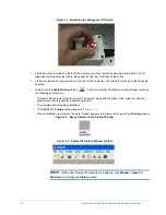
Page 58: ...ample This exercise continues in Chapter 4 which describes single scan operation and Chapter 5 which describes multiple scan operation By completing the entire exercise you will become comfortable the basic operational procedures of the Dektak 150 system START SEQUENCE The following sections describe the basic procedure for starting the Dektak 150 Power On To power on the system 1 Verify that all ...

Page 59: ...icon to start the Dektak 150 software As the software launches the following events occur The tower moves to its upper limit switch The system stops with the stylus in the tower up position allowing you to safely position a sample beneath it The sample positioning stage initializes The Dektak 150 Startup window appears Figure 3 3 When initialization is complete the word Ready appears in the lower ...

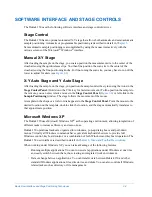
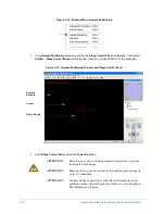
Page 60: ...e Stage Control Panel Figure 3 6 or left click in the Sample Positioning window The stage follows the movement of the mouse A template in the shape or a wafer or disk appears in the Stage Control Panel Point the mouse to the desired location on the template double click the location and the stage automatically translates to that approximate position Microsoft Windows XP The Dektak 150 uses Microso...

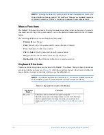
Page 61: ... Select Quickly press and release the mouse button Drag Hold down the left button while moving the mouse Double click Click the left mouse button twice in rapid succession Keyboard Shortcuts Numerous shortcut keystrokes are provided in the Dektak 150 software Many of these shortcuts are associated with menu items see Chapter 8 while others perform the same functions as clicking the mouse button on...

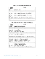
Page 62: ...ey s Function Up Arrow Increases illumination on the sample Down Arrow Decreases illumination on the sample Left Arrow Increases magnification Right Arrow Lowers magnification Ctrl Shift L Moves stage to center of rotation Ctrl V Moves stage to currently active scan routine s scan location Ctrl Shift U Moves stage to unload position When Stage Tracking is active press and hold Shift key for faster...

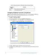
Page 63: ...ion to a keystroke 1 Click Setup Configuration Settings 2 Enter the password dektak32 to open the Configuration Settings dialog box 3 In the User Interface section click the Shortcuts icon to open the Shortcuts dialog box Figure 3 4 Configuration Settings Menu Shortcuts Dialog Box 4 In the F11 or F12 field select an analytical function from the drop down list 5 Click Apply and then click OK to ass...

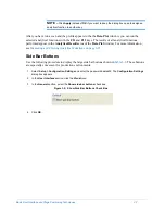
Page 64: ... Analytical Results area of the Data Plot window For more information see Measuring and Entering Analytical Functions on page 6 15 Side Bar Buttons Use the following procedure to display the large side bar buttons shown in Table 3 1 These buttons are especially convenient for production environments 1 Select Setup Configuration Settings and enter the password dektak32 The Configuration Settings di...

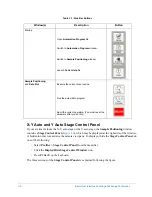
Page 65: ...the Stage Control Panel do one of the following Select Profiler Stage Control Panel from the menu bar Click the Display Hide Stage Control Window icon Press CTRL T on the keyboard The three sections of the Stage Control Panel are explained following the figure Window s Description Button Startup Open Automation Program file Switch to Automation Program window Switch to Sample Positioning window La...

Page 66: ... Control Panel Figure 3 7 contains an illustration of the template you have chosen for your application see Using the Templates Feature on page 3 13 The crosshairs provide a visual representation of the rotation theta of the stage Any scan sites that you have defined are shown as red dots The green dot shows the current location of the stylus on the sample ...

Page 67: ...ntrol Panel The center section of the Stage Control Panel Figure 3 8 contains three categories of templates disc wafer and panel along with any templates that you have designed A 150 mm wafer is already provided Right click in this section to open the Template Editor dialog box see Figure 3 10 where you can modify and save existing templates and create new ones Each template is saved to the config...

Page 68: ...ions select the Relative check box otherwise the movement will be to the absolute positions that you specify The units are in microns NOTE Since the camera is mounted on the X Y auto stage at the right side of the stylus the physical motions stage are at right angles to the motions of the image of your sample that you see in the camera view pane see Table 3 2 Table 3 2 Stylus Motions and Resulting...

Page 69: ... the template you want to change 2 Be sure the template you want to change is displayed in the fields at the left side of the dialog box If not click the name of the desired template in the Available Templates section 3 Make your changes to the parameters of the selected template and click Change 4 Click the close box at the upper right corner of the dialog box or press the ESC key on the keyboard...

Page 70: ...plate for your sample 1 If the Stage Control Panel is not displayed in the Sample Positioning window press CTRL T or click the Display Hide Stage Control Window icon 2 Click the name of the desired template in the Template Selection section of the Stage Control Panel Double click the name of a template type to display templates stored under that type 3 The selected template appears in the Template...

Page 71: ...le Positioning Window with Stage Control Panel 5 In the Stage Control Panel select the Tower Up button ATTENTION Raise the tower prior to loading samples to protect the stylus and the sample from damage ATTENTION Remonter la tour avant d installer les échantillons pour protéger le stylet et l échantillon ATTENTION Vor dem Auflegen einer Probe sollte die Abtastspitze nach oben gefahren werden um Ab...

Page 72: ...limit switch has been modified you may need to adjust it The Dektak 150 has four inches of clearance Positioning the Vertical Standard You must position the vertical standard so that the scan travels over the hill down into the calibration groove and then back again as shown in Figure 3 14 The scan must be at least 2500 µm long When the vertical standard is correctly positioned on the stage it app...

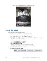
Page 73: ...with the arrow keys on the keyboard Hold down the CTRL key for faster motion The left arrow key moves the stage to the left The right arrow key moves the stage to the right The up arrow key moves the stage to the front The down arrow moves the stage to the rear Adjust the illumination on the sample Press the Up arrow on the keyboard or keypad to increase illumination Press the Down arrow on the ke...

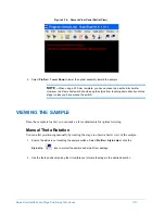
Page 74: ...down directly onto the stage unless you have moved the switch VIEWING THE SAMPLE Once the sample is loaded you can make a few adjustments for optimal viewing Manual Theta Rotation You can alter positioning manually by rotating the stage to obtain a better view of the sample 1 Ensure the stylus is not touching the sample surface Select Profiler Stylus Up or click the Stylus Up icon to protect the s...

Page 75: ...with the surface at the center of the reticule for easy sample positioning 1 Raise or lower the stylus using the toolbar icons see Figure 3 18 or the Profiler menu Click Profiler Stylus Up or Profiler Stylus Down see Figure 3 19 NOTE The Tower Up and Tower Down commands raise or lower the entire tower assembly which includes the USB camera illuminator and stylus mechanism The Stylus Up command lif...

Page 76: ...en first try adjusting the optics a much easier procedure before attempting to adjust the reticule To adjust the camera position see Adjusting the Optics on page 9 17 The stylus reticle can be aligned to a newly installed stylus or to allow for tolerances in the stylus head If the stylus tip is not properly aligned with the reticle in the camera view pane adjust the reticle position The reticle pr...

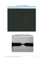
Page 77: ...eticule to the original default location in the center of the screen 3 Select Align to display the crosshair box Figure 3 21 The stylus touches down on the surface ready for alignment 4 Align the crosshair with the stylus tip Figure 3 22 and then double click the left mouse button 5 In the dialog box that appears click Yes to update the stylus reticule location No to retry the alignment or Cancel ...

Page 78: ...Basic User Interface and Stage Positioning Techniques 3 21 Figure 3 21 Stylus Reticle Alignment Figure 3 22 Stylus Tip Aligned with Crosshair ...

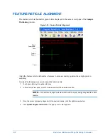
Page 79: ... the sample prior to scanning Complete the following procedure to realign the feature reticle 1 Touch down to bring the optics into focus 2 In the camera view pane move the mouse pointer to the desired location NOTE For best results align the feature reticle with a unique easily recognizable surface feature 3 Once the cursor is properly aligned with the desired feature click the right mouse button...

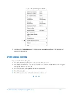
Page 80: ...ocation POWERING DOWN To power down the Dektak 150 system 1 Select File Exit from the Dektak menu bar to exit the Dektak software 2 Select Start Shut Down from the Windows XP Start menu and then click Shut Down in the dialog box that appears This exits Windows XP 3 Turn off the power by pressing the black button on the EMO box 4 Turn off the computer 5 Turn off the power switches on the optional p...

Page 81: ......

Page 82: ...to use the vertical standard that came with your system remove it from its case according to the instructions in Adjusting the Optics on page 2 23 Load the vertical standard or another sample on the stage according to the instructions in Sample Loading and Unloading on page 3 13 MAKING YOUR CONFIGURATION SETTINGS This section tells you how to change your configuration settings prior to a scan NOTE...

Page 83: ...the settings available from the icons in the Hardware section of the Configuration Settings window should not be changed by the user For help contact Veeco Technical Support CREATING A SINGLE SCAN AUTOMATION PROGRAM Prior to running a scan routine you must first create an automation program Automation programs are files that contain all the necessary information for performing single or multiple s...

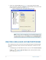
Page 84: ...tion program first select File Save As on the menu bar and enter a new file name for the modified program Then select File New NOTE If you select Window Automation Programs from the system menu bar the current automation program opens if there is one otherwise the default automation program opens Figure 4 2 New Automation Program The Automation Program window contains a default scan routine You ca...

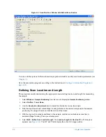
Page 85: ...oning from the menu to display the Sample Positioning window 2 Select Profiler Tower Down 3 Use the Illumination Adjustment icons to adjust the illumination to view the sample 4 With the stylus tower down initiate Stage Tracking left click in the camera view pane for fine sample positioning The image should now track the motion of the mouse 5 With the stylus reticle properly positioned on the samp...

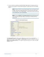
Page 86: ...ses of this exercise click the Enter button in the Length section to assign the length determined with Stage Tracking to this scan routine Note that it is also possible to edit the value with the keyboard 11 In the Current Length field which shows the length that you determined with Stage Tracking change the length to 1000 μm Click Enter to assign the new length value to the scan routine NOTE A sc...

Page 87: ...lick Apply only to accept an entry and keep the Scan Parameters dialog box open RUNNING A SCAN ROUTINE To run a scan routine click the Run Currently Active Scan Routine icon Alternatively press the F4 key or select Run Scan from the menu to run a scan routine The following sequence of events occurs after you initiate a scan The Data Plot window appears with the scaled grid superimposed over the ca...

Page 88: ...d on the monitor should resemble Figure 4 6 which includes the following elements in addition to scan profile and reference measurement cursor functions List of user set scan parameters List of analytical results if any analytical functions were selected for this scan A Watch List which provides real time monitoring of ASH delta average step height horizontal distance and vertical distance NOTE On...

Page 89: ...eters measurement parameters ranges and analytical function calculations all appear in the new units that you have specified You can toggle the type of notation between Fixed and Scientific The system automatically determines the number of decimal places as follows Angstroms no decimal places Microns four decimal places Nanometers one decimal place To change units before or after a scan 1 On the S...

Page 90: ...hat you do not use zero 0 bandwidths unless you want point to point measurements Such measurements can vary substantially from the averaged results that you get with non zero bandwidths BASIC CURSOR POSITIONING Cursor positioning is critical for obtaining accurate results The simplest way to reposition the cursors is to use the mouse to drag the R and M cursor flags at the top of the cursors to ne...

Page 91: ...ds Figure 4 9 Setting Default Cursor Band Widths SETTING CURSOR BANDWIDTHS The simplest way to change the bandwidth of the cursors is to use the mouse to drag the double triangle handles at the bottom of the cursors to new widths in the data plot see Figure 4 10 NOTE When the cursors are near the edges of the plot the handles might not be visible To specify numerical values for the bandwidths sele...

Page 92: ...rofile trace in relation to the vertical scale Figure 4 11 Data Plot Box Special cursor control arrow buttons at the bottom right of the Data Plot display allow you to work with the cursors see Figure 4 12 You can position the cursors by selecting a cursor and then clicking and holding the left and right arrow buttons Similarly you can increase or decrease the selected cursor s bandwidth by clicki...

Page 93: ...ter new values in these boxes NOTE For this exercise the location of the R cursor should be set at 100 µm with the M cursor at 900 µm 1 Click in the upper white box indicating the R cursor horizontal Position A blinking prompt appears in the box 2 Enter 100 using the keyboard and press ENTER The R cursor repositions at 100 µm 3 Click in the lower white box indicating the M cursor horizontal Positi...

Page 94: ...appear totally within the graphic boundaries to achieve the minimum acceptable manual leveling If not repeat the manual leveling procedure above NOTE For maximum performance of the Dektak 150 it is important to position the sample surface to within 0 01º of level Use the formula tan 1 slope of leveled trace to determine the level accuracy To verify that the maximum possible level has been obtained...

Page 95: ...software level the stage in order to obtain accurate step height measurements or accurate readings from analytical functions Software leveling sets the reference and measurement cursors at zero to establish a reference for measurements Complete the following steps to software level a trace 1 Position the R and M cursors along the baseline of the step 2 Click the Level icon press F7 or select Plot ...

Page 96: ...keyboard to automatically replot the profile trace and establish the zero point at the R cursor intercept see Figure 4 15 Figure 4 15 Setting the Zero Point MAKING A DELTA AVERAGE STEP HEIGHT MEASUREMENT Once you run the scan routine and leveled the profile you can obtain an accurate vertical measurement of the calibration standard using the Delta Average Step Height analytical function Analytical...

Page 97: ...TE The Measure and Measure Program buttons enter the ASH function into the current scan routine to be performed automatically when the current scan routine runs again 5 Click Compute to calculated the average step height The value appears in the Analytic Results area at the left side of the Data Plot window 6 Click the Run Currently Active Scan Routine icon the F4 key or select Run Scan from the m...

Page 98: ...area of the Data Plot window you want magnified and left click on that location Hold down the mouse button 3 Drag the mouse away from the first corner at a diagonal to expand the box 4 Release the mouse button when the box covers the area of interest For this exercise the boundaries should look similar to those shown in Figure 4 18 In the Plot menu that appears you can choose Replot to replot the ...

Page 99: ...and Graphics Do one of the following Select the Save as Image option to open a dialog box that allows you to save the currently displayed data plot in your desired graphics format Figure 4 19 Select Video Graphics Only to save only the data plot Select Video Video and Graphics to display the live video behind the data plot After viewing this display select Save as Image to save the currently displ...

Page 100: ...ation program information the Automation Program Summary Report and the Watch List using a Windows compatible printer Select File Print press CTRL P or press the F10 key to display a standard Windows dialog box listing various printer options or Click the Print Scan Data and Parameters icon to produce a printout on the currently active printer NOTE Drivers for the Windows compatible printer must b...

Page 101: ... an automation program but do not save it according to the steps in this section you will be asked if you want to save it when you exit the program For more information see Saving upon Exiting the Dektak Program on page 4 23 1 Click the Automation Program icon or select Window Automation Programs from the menu bar to display the Automation Programs window see Figure 4 20 Figure 4 20 Automation Pro...

Page 102: ...ion program is now saved on the hard disk under the designated file name ABORTING AN OPERATION To abort a Dektak 150 operation select an Abort icon or press the Esc or A key on the keyboard NOTE If you abort an operation while the stage is rotating you must reset the hardware by selecting Profiler Reset Hardware from the menu or pressing CTRL ALT R on the keyboard ...

Page 103: ...is plot with routines such as Terms Removal Tilt Curvature Sphere and others Masking both Analysis and Terms Histogram Plot Bearing Ratio Plot Processed Options For illustrations and explanations of the above routines see Appendix E To open a Dektak 150 scan in Vision 1 Open Vision 2 From the File menu select File Open Stored Dataset 3 Navigate to the Dektak Data folder and click the file that you...

Page 104: ...e following prompts may appear Do want to store analytical results to the scan routine Do you want to save the current scan data and analytical functions results Do you wish to save your changes to the current automation program If you click Yes at the last two prompts a Save File dialog box appears Use this dialog box to name your file and specify where you want to save it NOTE For more informati...

Page 105: ......

Page 106: ...in Adjusting the Optics on page 2 23 Load the vertical standard or another sample on the stage according to the instructions in Sample Loading and Unloading on page 3 13 ABOUT THE AUTOMATION PROGRAM The automation program is the basis for all operations performed on the Dektak 150 The Automation Program window displays the current scan routines along with their X and Y locations as well as data de...

Page 107: ...ault prog displayed see Figure 5 1 2 If an automation program to which you have made changes is currently open a dialog box asks if you want to save those changes Click Yes to save your changes to the current automation program NOTE Be aware that if the current automation program was previously loaded and then modified it will be saved under its original file name If you want to preserve the origi...

Page 108: ...utine and selecting Copy to Range Furthermore you can open a dialog box that allows you to copy a single scan routine by clicking the Copy Currently Selected Scan Routine icon selecting Edit Copy Currently Selected Scan Routine pressing the CTRL C key combination or right clicking on the scan routine in the box on the right side of the window and selecting Copy To Figure 5 2 Copy to Range Dialog B...

Page 109: ...5 4 Scan Routines Area with Scan Routine Selected At this point all four scan routines in your current automation program have the same values You can use the functions described in the next section to determine new values for the location and length of each scan routine in the Sample Positioning window Furthermore you can adjust or edit values for each scan routine in the Scan Routines window usi...

Page 110: ...on 5 5 Figure 5 5 Sample Positioning Window for Default Program Routine 3 2 Select Profiler Tower Down see Figure 5 6 or click the Tower Down to Null Position Stylus Up icon Figure 5 6 Profiler Menu with Tower Down Selected ...

Page 111: ...n the keyboard The Location Length for Routine 3 of 4 dialog box appears see Figure 5 7 The X and Y fields display the current X Y auto stage position Do one of the following Click Enter to store the current location Change the position of the stage by using the mouse keyboard or Stage Control Panel and then click Enter Figure 5 7 Scan Location Length Dialog Box 8 Click the Enter button in the Cur...

Page 112: ...appears to be moving from the bottom to the top during the scan Figure 5 10 Automation Program Window with Parameters for Routine 2 c Click the Enter button in the Scan Browser section or use the button to select the next scan routine as the currently active scan routine d Select Profiler Tower Down e With the stylus tower down initiate Stage Tracking left click in the camera view pane for fine sa...

Page 113: ...ant to scan m Roll the mouse until the stylus reticule is at the end of the scan and then click the left mouse button to deactivate Stage Tracking The Current Length section Location Length for Routine 1 of 4 dialog box now shows the length of the scan that you determined with Stage Tracking You can accept the value shown or edit the value with the keyboard Click the Enter button in the Current Le...

Page 114: ...Multiple Scan Operation 5 9 Figure 5 12 General Tab of the Automation Program Options Dialog Box Figure 5 13 Extended Tab of the Automation Program Options Dialog Box ...

Page 115: ...ow along with the total number of scan routines in the automation program see items circled in magenta in Figure 5 14 Figure 5 14 Scan Routines Window The scan routine shown in the Scan Routines window is the routine that you selected in the Automation Program window There are several ways to display the other scan routines in this window without returning to the Automation Program window Click th...

Page 116: ... to open the Go To Scan Routine dialog box see Figure 5 9 where you can type a scan routine number Then press the Enter key Editing Scan Routines You can edit a scan routine by clicking any underlined parameter in the Scan Routines window see Figure 5 14 Scan Parameters Click any of the underlined parameters in the Scan Parameters section to open the Nominal Parameters tab of the Scan Parameters d...

Page 117: ...only if the 3D Mapping option has been installed Use it to set the parameters for a 3D map scan The Dektak 150 software allows you to include both standard scans and map scans in a single automation program For more information see Appendix E Figure 5 19 Map Parameters Tab of the Scan Parameters Dialog Box Previous and Next buttons ...

Page 118: ...Figure 5 20 Figure 5 20 Leveling Tab of the Display Parameters Dialog Box Use the Leveling tab to determine whether or not the system should automatically remove tilt from the trace based on the defined cursor location and width Click R Cursor or M Cursor to open the Cursors tab see Figure 5 21 Figure 5 21 Cursors Tab of the Display Parameters Dialog Box Use the Cursors tab to set new values for c...

Page 119: ...o enable the system to automatically determine the vertical range or to select Set Range Values and enter your own Lower Bound ary and Display Range values When you enter values in the Lower Bound ary and Display Range fields the scan shown in the Data Plot window updates on the fly Click Display Data Type to open the Type tab see Figure 5 23 Figure 5 23 Type Tab of the Display Parameters Dialog B...

Page 120: ... Select one of the entries in the Data Processing section of the Scan Routines window to open the corresponding tab of the Data Processing Parameters dialog box When you enter your data processing filtering settings as a scan parameter the system automatically performs data processing filtering during a scan You can change these data processing filtering parameters at the end of a scan NOTE In the...

Page 121: ...cally applied to each analysis that is run under a scan routine that includes them For information about the wavelength filter cutoffs see Determining the Cutoff Wavelength on page 6 10 Click Smoothing to open the Smoothing tab of the Data Processing Parameters dialog box see Figure 5 26 Figure 5 26 Smoothing Tab of the Data Processing Parameters Dialog Box Set in order to specify Rough ness in th...

Page 122: ...g box to select the analytical functions to be appended to the scan routine See Chapter 6 for details Figure 5 27 Edit Menu with Append Analytical Functions Selected For details on filters see For details on smoothing see Determining the Cutoff Wavelength on page 6 10 Using the Smoothing Function on page 6 18 Activating the Cutoff Filters on page 6 11 Activating the Smoothing Function on page 6 19...

Page 123: ...orts on page 5 27 Global Editing of Scan Routine Parameters You can change individual scan parameters within each scan routine of an automation program at any time Use the Global Edit Mode to edit the parameters of all the scan routines simultaneously within the automation program To become familiar with the Global Edit Mode follow the steps below It is assumed you are still working with your new ...

Page 124: ...ion program Click YES to continue A global edit symbol similar to the one shown in Figure 5 29 appears Click an entry in the Display Parameters section to open the Display Parameters dialog box 3 On the Leveling tab select the Automatic Leveling check box see Figure 5 30 Figure 5 30 Leveling Tab with Automatic Leveling Selected 4 On the Cursors tab enter 50 into each Width field see Figure 5 31 ...

Page 125: ...g box 7 Enter 300 in the R Cursor Width field and enter 900 in the M Cursor Width field see Figure 5 32 Figure 5 32 Cursor Positioning Section of the Analytical Functions Dialog Box 8 In the Height section of the Available panel select ASH see Figure 5 33 Figure 5 33 Height Section with ASH Selected 9 Click Add and then click Done see Figure 5 34 to append the analytical function see Figure 5 35 ...

Page 126: ...5 35 Analytical Function Appended 10 To disable Global Edit Mode either Click the Global Edit icon Select Edit Global Edit Mode from the menu bar see Figure 5 36 Right click in the window and clear the check from the Global Edit Mode option Figure 5 37 Click Add and then click Done ...

Page 127: ...sired file location and file name The path of the file location is C Program Files Veeco DektakV9 Program unless you have changed it see Setup Menu on page 8 7 NOTE Your file name cannot have cannot contain more than 80 characters and must include the extension prog AUTOMATION PROGRAM OPTIONS You can select various options for the automation program to be performed at the conclusion of each scan r...

Page 128: ...ing option that allows you to pause before each scan until you decide to continue specify a time delay between scans or specify no pause between scans A Prompt at Run Time option that allows you to display the Title Notes dialog box at the beginning of each scan A Store with Scan Data option that directs the system to automatically save the Title Notes dialog box along with the scan data If you do...

Page 129: ...0 application When you save your data using the Data Export option you can export it as a csv file that can be opened in other data processing programs NOTE You can also save scan data using the Export ASCII Data dialog box as described in Exporting a Scan Data Plot on page 5 41 To save and export your scan data as a Data file 1 In the Automation Program Options section of the Automation Program W...

Page 130: ...t a data file or specify a new one For this exercise enter Exercise in the file name field Then click Select to close the dialog box Leave the other options at their default settings Figure 5 41 Scan Data Saved as a Dataset File Select the Select At Run Time check box to wait until the scan has run before you choose the file to save the scan data 3 In the Scan Data Export section see Figure 5 40 d...

Page 131: ...h directs the Dektak 150 software to compute the APS Report Click the button to open the Specify File dialog box see Figure 5 43 where you can select a report file or specify a new one for your APS Report Select the Select At Run Time check box to wait until the completion of a scan before choosing the file in which to save the APS Report Figure 5 43 Specify File Dialog Box for APS Summary Report ...

Page 132: ...ektak 150 application generates a plot for all analytical functions in the automation program It cannot plot only selected analytical functions At the end of the scan run you can use the APS Report to select and rerun only certain scan routines For instructions see Rerunning Selected Scans in the APS Report on page 5 32 Activating the APS Report Function 1 Make sure that all of the scan routines i...

Page 133: ... b In the File name field select an existing text file or specify a new one The extension report is automatically added c Click Select and then click Apply 6 If you want to specify the file in which to save the APS Report at the end of each scan run select the Select At Run Time check box 7 If you want the Dektak 150 application to automatically print the APS Report in landscape orientation on a s...

Page 134: ...g Box 8 In the Automation Program window select Run Auto Program see Figure 5 48 The APS Report for the current analytical function appears over the Data Plot window see Figure 5 49 For more information see Contents of the APS Report on page 5 30 Figure 5 48 Run Menu with Auto Program Selected ...

Page 135: ... The report extension is automatically appended To print an APS Report click the Print icon on the APS Report toolbar Alternatively select File Print Auto Program Summary APS Contents of the APS Report The APS Report includes a Grid View tab see Figure 5 50 providing information about all of the scan routines that have run in this animation program It also contains tabs displaying the final graphi...

Page 136: ...ors for each analytical function The second section lists the individual analytical function results for each scan routine The Summaries section summarizes the mean standard deviation minimum maximum and range of the analytical function for all the scan routines Plot Tabs of the APS Report Each Plot tab see Figure 5 50 of the APS Report shows the final plot that was generated for that analytical f...

Page 137: ...rerun selected scans in the APS Report 1 In the list of scan routines on the Grid View tab Figure 5 52 do one of the following Left click the mouse on the left button to select an entire row Use the CTRL key on the keyboard along with the left mouse button to select multiple rows Use the SHIFT key on the keyboard along with the left mouse button to select two rows and all of the rows in between Pr...

Page 138: ...cs are also updated Selecting a Rerun Scan for Viewing When the APS Report for each rerun scan is saved it does not overwrite the APS Reports for the previous reruns Instead each report is given a Date Time stamp and saved individually To display a selected APS Report 1 Select the desired time stamp from the drop down list to the left of the Update button 2 Click the Update button see Figure 5 53 ...

Page 139: ...se or navigate to C Program Files Veeco DektakV9 Data dektakdatabase exe 2 Double click the APS Report file that you want to open Exporting an APS Report to Excel To export an individual APS Report to Microsoft Excel 1 Do one of the following Click the Export to Excel icon on the APS Report toolbar Right click the APS Grid tab see Figure 5 50 and point to Export to Excel The Specify File dialog bo...

Page 140: ... the arcing motion of the stylus This increases the accuracy for the slope calculation the area and volume calculations and any other analysis that requires a highly accurate lateral and slope calculation The algorithm is based on the length of the stylus tip and the length of the stylus area added to the privot point in the sensor These values are controlled tightly in production and do not vary ...

Page 141: ...In the User Interface section click Data Processing The Data Processing settings appear see Figure 5 58 Figure 5 58 Configuration Settings Dialog Box with Data Processing Settings Displayed 4 In the Micro Form Measurement section select the Enable check box see Figure 5 59 ...

Page 142: ...r Output Section of the Extended Tab Make one or more of the following selections Select None to prevent the printer from producing any printouts Select Print Plot to print the plotted profile trace after each completed scan routine along with the scan data The plot prints on a single page Select Print APS to print the Automation Program Summary Report in landscape orientation on a single page For...

Page 143: ...ct Delay to open the Pause Automation Program dialog box see Figure 5 62 and enter the number of seconds for a time delay that will occur between scans Figure 5 62 Pause Automation Program Dialog Box Select Run Continue see Figure 5 63 from the menu bar to move to the next scan routine in the sequence contained in the automation program Figure 5 63 Run Menu with Continue Selected ADDING USER INFOR...

Page 144: ...e Title Notes dialog box at the beginning of each scan that you run using an automation program If desired enter information in the Title Notes dialog box that will appear by default at the beginning of each scan To do this click Editor and enter your information in the Title and Notes fields see Figure 5 65 Typically this information indicates the part the operator the tool the process or other m...

Page 145: ...ace plots on the scaled grid in real time see Figure 5 66 NOTE With many camera setups during a scan the video image shows the sample moving from right to left below the stylus In actuality the stage is moving from back to front Once the first scan is complete the stylus lifts off the surface and the stage resets to the starting point of the next programmed scan When the final scan is complete the...

Page 146: ... generate roughness and waviness scan data you can export that data along with the raw data For more information see Display Parameters on page 5 13 1 Click the Export Scan Data icon or select File Export The Export ASCII Data dialog box appears 2 Click the Data folder and navigate to the file s you want to export 3 In the Save in field navigate to the location where you want to save the files 4 M...

Page 147: ... at the conclusion of the automation program to retrieve the data plots through the Load File dialog box see Figure 5 68 3 Under Files of type confirm that Auto has been selected This displays all stored Dektak 150 files including data and program files NOTE The data plot from scan routines 1 2 3 and 4 are filed under Exercise 001 dat Exercise 002 dat Exercise 003 dat and Exercise 004 dat respecti...

Page 148: ...work with the automation program and scan data after the scan see the following sections Printing the Scan Data on page 4 19 Saving an Automation Program on page 4 20 Opening a Dektak 150 Scan in Vision on page 4 22 Saving upon Exiting the Dektak Program on page 4 23 ...

Page 149: ......

Page 150: ...ersions of the Analytical Functions dialog box depending on the window that is active when the dialog box is opened To open the Analytical Functions dialog box from the Scan Routines window click the Append Analytical Functions to Current Scan Routine icon or select Edit Append Analytical Functions from the menu bar See Figure 6 16 For further information on this version of the Analytical Function...

Page 151: ...www asme org ROUGHNESS PARAMETERS The following parameters are listed alphabetically Maxdev Maximum Deviation Calculates the furthest data point above or below the mean line MaxRa Maximum Ra Identifies the portion of the assessment length that has the highest Ra The assessment length defined by the cursors divides into nineteen overlapping segments Each segment is equal to one tenth of the assessm...

Page 152: ...ment length that has the highest Ra The assessment length defined by the cursors divides into nineteen overlapping segments Each segment is equal to one tenth of the assessment length distance The Ra is calculated for each segment The R cursor positions in the center of the segment with the highest Ra You can program only one MaxRa into a scan program Ra Average Roughness Formerly known as Arithme...

Page 153: ...Rq Roughness Analytical Function Rt Maximum Peak to Valley The sum total of the maximum peak and maximum valley measurements of roughness within the assessment length Rt Rp Rv see Figure 6 4 Figure 6 4 Rt Roughness Analytical Parameters Rv Maximum Valley The lowest point or the maximum depth of the profile roughness below the mean line within the assessment length see Figure 6 5 Rt Rp Rv Rt is the...

Page 154: ...4768 1 specification published by the Deutsche Institut fuer Normung c v see Figure 6 6 Figure 6 6 Rz Roughness Analytical Parameter Skew Skewness The symmetry of the profile about the mean line It distinguishes between asymmetrical profiles of the same Ra or Rq Skewness is non dimensional NOTE For best results software level the scan trace prior to calculating any analytical functions RSK 1 LRq 3...

Page 155: ...p Maximum Peak of Waviness Measures the maximum height of the highest peak of the waviness profile above the mean line Corresponds to Rp Wq Root Mean Square of Waviness Determines the root mean square RMS value of waviness Corresponds to Rq Wt Maximum Peak to Valley of Waviness The sum total of the maximum peak and maximum valley measurements of waviness Wt Wp Wv Corresponds to Rt Wv Maximum Valle...

Page 156: ...ne of the assessment length Pc is expressed in peaks inch or peaks cm Peak Maximum Peak Calculates the maximum height above the baseline as determined by the cursor trace intercepts P_V Maximum Peak to Valley Calculates the vertical distance between the maximum peak and maximum valley TIR Total Indicated Reading Calculates the vertical distance between the highest and lowest data points between th...

Page 157: ...ts the upper edge of the step before the lower edge and the slope measurement will be inaccurate Sm Mean Spacing Between Peaks Calculates the mean spacing between peaks as defined by downward crossing of the mean line followed by an upward crossing to the next downward crossing If the distance between these downward crossing points is less than 1 percent of the measurement length then this peak is...

Page 158: ... on the raw profile data is described below The analytical function domain is on the data between the R and M cursors You can relocate the cursors if desired but for this exercise use the default cursor setting of 100 and 1900 µm for a 2 mm scan 1 Select Analysis Analytical Functions to display the Analytical Functions dialog box with selections for setting roughness waviness heights and geometry ...

Page 159: ...cut off wavelength must be less than the scan length Also the cutoff value will not be accepted if fewer than eight data points are available per cutoff wavelength The Scan Resolution parameter displayed in the Scan Routines window provides the number of µm per sample for a given scan length and speed The minimum acceptable cut off wavelength must be at least eight times longer than the value list...

Page 160: ...s data filtering out high frequency roughness signals and allowing low frequency waviness data to pass through Band Pass Filter When you select the band pass filter both the short pass and long pass filters are enabled to calculate the roughness data creating a band that filters out high frequency signals above the band and low frequency signals below the band ACTIVATING THE CUTOFF FILTERS To obta...

Page 161: ...he short pass and long pass filters into the scan routine to automatically calculate the roughness and waviness analytical functions 1 Select Window Scan Routines to open the Scan Routines window 2 In the Data Processing section click Filter Cutoffs to open the Filter Cutoffs tab of the Data Processing dialog box see Figure 6 12 3 Enter a cutoff value of 200 µm in the Short Pass Filter Cutoff box ...

Page 162: ...ata to display in the Data Plot window You can display the raw roughness and waviness profile data either individually or simultaneously 1 Select Plot Data Type to display a dialog box for selecting the raw roughness or waviness data type NOTE All three selections should be activated as indicated by their respective check boxes see Figure 6 13 ...

Page 163: ...u can predetermine the type of profile data to display at the conclusion of a scan by entering the selected data types into the scan routine 1 In the Display Parameters section of the Scan Routines window click Display Data Type to open the Type tab of the Display Parameters dialog box As shown in Figure 6 14 here you can select from three display options raw roughness and waviness Figure 6 14 Typ...

Page 164: ...t window to be automatically calculated whenever the current scan routine runs In the exercise that follows you will learn the procedure for measuring the Ra function and entering it into the scan routine 1 Select Analysis Analytical Functions from the Data Plot window to open the Analytical Functions dialog box see Figure 6 15 at the left NOTE You can also open the Analytical Functions dialog box...

Page 165: ... 15 Analytical Functions Dialog Box and Results Data Plot Window Figure 6 16 Analytical Functions Dialog Box from Scan Routines Window Analytical Functions Dialog Box from Data Plot Window Analytical Results Section of Data Plot Window ...

Page 166: ...ns to Current Scan Routine icon to display the Analytical Functions dialog box 3 Under Waviness in the Analytical Functions dialog box click Wa 4 Set the cursors at different locations for each individual analytical function Enter 0 in the R Cursor box Enter 1900 in the M Cursor box Click Add 5 Click Done As shown in Figure 6 17 Waviness on appears in the Analytical Functions area on the right sid...

Page 167: ...ch as those that have films deposited over rough substrates The substrate roughness transfers to the film surface which can make measurements difficult or questionable You can apply smoothing in one of two ways In applications where rough samples will be run on a regular basis you can enter smoothing into the scan routine After you do this the smoothing function performs automatically on each scan...

Page 168: ...splay the Data Plot window with the replotted profile data 2 Select Analysis Analytical Functions to display the Analytical Functions dialog box 3 Under Height click TIR 4 Select Measure 5 Click Compute NOTE The total peak to valley distance is calculated 6 Select Analysis Smoothing to display a dialog box for entering smoothing parameters see Figure 6 19 7 Select one of three available degrees of...

Page 169: ...ction on the scan to be smoothed Follow the instructions in Activating the Smoothing Function on page 6 19 5 In the Band field enter a value that is equal to or greater than the TIR value shown in the Analytical Results area of the Data Plot window 6 Click OK to automatically smooth the profile data whenever the current scan routine executes 7 To clear smoothing enter zero 0 in the Band field of t...

Page 170: ...rameters and data processing parameters that are available in the Scan Routines window Figure 7 1 Scan Routine Window You can enter up to 10 000 different scan routines into a single automation program file Each scan routine within an automation program contains all the necessary parameters for performing a ...

Page 171: ...meters tab of the Scan Parameters dialog box Here are some guidelines for using this dialog box After you select a scan parameter click OK to add it into the scan program Alternatively you can click Apply to enter the scan parameter into the scan program but keep the dialog box open to make additional entries If your system includes options that create their own tabs in the Scan Parameters dialog ...

Page 172: ...in your system 1 Click any parameter in the Scan Parameters section of the Scan Routines window see Figure 7 1 to display the Nominal Parameters tab of the Scan Parameters dialog box 2 In the Stylus Type section see Figure 7 4 choose the desired stylus type from the drop down list 3 Click OK to close the dialog box and enter the stylus type into the scan program NOTE The Stylus Type parameter does...

Page 173: ...he optional x y auto stage 1 Click any parameter in the Scan Parameters section of the Scan Routines window see Figure 7 1 to display the Nominal Parameters tab of the Scan Parameters dialog box 2 Click in the desired box labeled X or Y and enter the desired coordinates using the keyboard see Figure 7 5 3 Click OK to close the dialog box and enter the location into the scan program Appears only if...

Page 174: ... lengths from 50 µm to 55 000 µm 50 mm are possible using the standard Dektak 150 system 1 Click any parameter in the Scan Parameters section of the Scan Routines window see Figure 7 1 to display the Nominal Parameters tab of the Scan Parameters dialog box 2 In the Length field enter the desired scan length using the keyboard see Figure 7 6 NOTE The scan length is expressed in microns µm 3 Click O...

Page 175: ...ata points You can set the scan duration from 3 to 200 seconds for a maximum of 60 000 data points per scan Select a longer scan duration for long scan applications and measurements of very fine surface roughness requiring the highest horizontal resolution When high throughput is the primary consideration use a shorter scan duration For most applications a 10 20 second scan provides adequate resol...

Page 176: ...r the distance between data samples Therefore a scan routine with the lowest number of µm per sample provides the best possible horizontal resolution The Dektak 150 provides horizontal resolution with a maximum 60 000 data points available per scan Scan length and scan duration determine the horizontal resolution of the Dektak 150 The profiler maintains a constant sampling rate of 300 data points ...

Page 177: ...orce use low or medium scan speed in other words a longer scan duration at the shortest possible scan length To set the scan resolution 1 Click any parameter in the Scan Parameters section of the Scan Routines window see Figure 7 8 to display the Nominal Parameters tab of the Scan Parameters dialog box 2 In the Resolution field enter the desired scan duration in seconds using the keyboard see Figu...

Page 178: ...essive scan therefore uses the same initial reference point Static Scan A special scan type in which the scan is performed at the same point the stage does not move The tower is nulled before the scan This scan type is primarily used for determining the noise and drift of the system Map Scan The Dektak 3D Mapping Option allows Dektak surface profiler customers to measure analyze and view surface c...

Page 179: ...e available vertical resolution depends upon the Measurement Range selected When measuring extremely fine geometries the 65 kÅ range provides a vertical bit resolution of 1 Å For general applications the 10 Å vertical resolution of the 655 kÅ range is usually adequate When measuring thick films or very rough or curved samples select the 5240 kÅ range with 80 Å resolution 1 Click any parameter in t...

Page 180: ...tal grid line Used primarily for measuring etch depths Hills and Valleys Provides 50 of the measurement range above the zero horizontal grid line and 50 percent below Used in most applications especially if the surface characteristics of the sample are not well known or if the sample is out of level Hills Provides 90 of the measurement range above the horizontal grid line Used primarily for measur...

Page 181: ...log Box Profile When you are running scans to be plotted using the optional 3 D mapping feature described in Appendix E and your system includes the N Lite option described in Appendix F you can enable soft touchdown Soft touchdown gradually increments the stylus force up to the specified value which slowly lowers the stylus For information on making the soft touchdown settings see Appendix F ...

Page 182: ...e Tower dialog box which is available from the Configuration Settings dialog box See Hardware Settings on page 8 12 NOTE The Tower Up After Scan option is available only when the Soft Touchdown option is NOT selected 1 Click any parameter in the Scan Parameters section of the Scan Routines window see Figure 7 1 to display the Nominal Parameters tab of the Scan Parameters dialog box 2 In the Additi...

Page 183: ...ssive MEMS and cantilever devices subjected to different applied forces The Scan Type parameter allows you to specify which scan type to use 1 Click any parameter in the Scan Parameters section of the Scan Routines window see Figure 7 1 to display the Nominal Parameters tab of the Scan Parameters dialog box 2 In the Scan Type section select Deflection Scan from the list 3 In the Stylus Force secti...

Page 184: ...Nominal Parameters tab Interval is set at 1000 msec 1 second Increment is set at 0 05 mg End Force is calculated and displayed as 3 65 mg 13 seconds divided by 1 second multiplied by 0 05 mg 0 65 mg to be added in 0 05 mg increments to 3 mg DISPLAY PARAMETERS In its Display Parameters section the Scan Routines window contains parameters that allow automatic manipulation of the graphic display of t...

Page 185: ...play Parameters section of the Scan Routines window click Software Leveling see Figure 7 1 to open the Leveling tab see Figure 7 17 2 Select the Automatic Leveling check box and then click Apply 3 Click the Cursors tab see Figure 7 18 and make your settings according to these guidelines When the default band width is 0 the trace levels using only two points at the R and M Cursor locations If you k...

Page 186: ... settings directly into the scan routine in the Scan Routines window 1 In the Display Parameters section of the Scan Routines window see Figure 7 1 click R Cursor or M Cursor to open the Cursors tab see Figure 7 18 2 Enter the desired cursor location for the R and or M Cursor and then enter the Bandwidth values 3 Click OK to enter the cursor positions into the scan routine Entering Cursor Position...

Page 187: ...some applications where repetitive or like scans are compared you can preset the graphic scale by numeric entry 1 In the Display Parameters section of the Scan Routines window see Figure 7 1 click Display Range to open the Range tab see Figure 7 19 2 Do one of the following To allow the system to automatically set the range click Automatic Ranging To set the display range at a specified value clic...

Page 188: ...ure 7 20 Display Parameters Dialog Box Type DATA PROCESSING PARAMETERS These parameters allow you to filter and smooth your data as well as set the options for Step Detection analysis Filter Cutoffs The Data Processing section of the Scan Routines window includes the Filter Cutoffs tab which contains options that allow you to activate filter cutoffs Figure 7 21 For a full description of the Filter...

Page 189: ...a Processing section of the Scan Routines window includes the Smoothing tab which contains options that allow you to activate smoothing filters Figure 7 22 For a full description of the smoothing filters see Data Processing Settings on page 5 15 Figure 7 22 Data Processing Filter Smoothing Tab ...

Page 190: ...window includes Step Detection settings which appear on the General Settings tab Figure 7 23 and the Every Step tab Figure 7 24 For instructions on making setting for Step Detection analysis see Appendix D Figure 7 23 Step Detection General Settings Tab Figure 7 24 Step Detection Every Step Tab ...

Page 191: ......

Page 192: ...50 windows and the status bar appears at the bottom Each Dektak 150 window has its own specific menus and tool bars These menu items and toolbar icons are described in the following sections STARTUP WINDOW When no other window is active in the Dektak 150 application the Startup window appears As shown in Figure 8 1 it contains a default menu bar toolbar and status bar Figure 8 1 Dektak 150 Startup...

Page 193: ... Ctrl N means hold down the Ctrl key press and release the N key and then release the Ctrl key Additional Menus Most of the other windows contain at least one menu in addition to those that appear on the default menu bar These menus are described in the sections that follow Toolbar Each window contains a unique toolbar consisting of a set of icons to perform various functions You can open some men...

Page 194: ...he current automation program If the Data Plot window is active scan data is saved If the Dektak Database window is active the APS Report is saved The Save As command by default saves an automation program under a different file name Select File Save As to display a list of file names currently in use and enter a new file name to use If the Data Plot window is active scan data is saved under a dif...

Page 195: ... under a different file name Select File Print to print a form appropriate for the active window If there is no predefined form for the window the print function acts as a print screen command printing the entire current active screen Opens Windows Explorer at the active directory Veeco Dektak32 by default Closes the Dektak 150 application after confirmation RUN MENU This menu runs a scan routine ...

Page 196: ...s Select Run Continue to run the next scan in sequence of a multiple scan automation program when the autoprogram function Adjust Position Before Each Scan has been activated Select Run Continue to continue at the next scan in sequence of a multiple scan automation program when the automation program was aborted during a scan NOTE If you abort the operation while moving the stage the stage positio...

Page 197: ...e user to view the video image of the sample surface while positioning the stage without contact between the stylus and sample Select Stylus Down to lower the stylus onto the sample surface unless the tower is already in the home position The tower and stylus automatically raise a small amount off the sample surface whenever the sample stage repositions Select Profiler Reset Hardware for a complet...

Page 198: ...ey or enter the password in the dialog box to open the Configuration Settings dialog box As shown in Figure 8 5 this dialog box includes two sections User Interface and Hardware NOTE Click OK after making your selections to close the dialog box Click Apply instead of OK if you want to keep the dialog box open to click other icons Figure 8 6 Configuration Settings Dialog Box Manual Leveling Configu...

Page 199: ...and 3D map files Select the Make shortcuts available system wide check box if you want icons for the directories to appear in file dialog boxes such as Open Save and Save As Figure 8 7 Directories Dialog Box Data Processing These settings allow you filter the data with a line fit or low pass filter They also allow you to enable MicroForm Measurement see Enabling MicroForm Measurement on page 5 35 ...

Page 200: ... Dialog Box Shortcuts This dialog box allows you to ace the drop down list see Figure 8 10 to assign an analytical function to the F11 and F12 keys For more information see Assigning Analytical Functions to Keystrokes on page 3 6 Figure 8 9 Shortcuts Dialog Box ...

Page 201: ...troms um or nm In the Notation section select Fixed or Scientific The system then makes the appropriate Decimal Places setting This field cannot be modified by the user NOTE You can change the units in which information is displayed before or after a scan For more information see Changing Units Before or After a Scan on page 4 8 ...

Page 202: ...og Box Visual In the General section click Show Sidebar Buttons to display them on the screen Different buttons are available for each screen For more information see Side Bar Buttons on page 3 7 Figure 8 12 Sidebar Buttons in Data Plot Window Sidebar buttons ...

Page 203: ... and Soft Touchdown settings which are discussed in this section NOTE After you change Dektak 150 hardware settings a few seconds of delay occurs while the system downloads the parameters into the E box Illumination This dialog box allows you to set the increment to be used when changing the sample illumination see Stylus Reticle Alignment on page 3 19 Enter a value between 1 and 255 for the Illum...

Page 204: ...d for calibrating various operations of the system Figure 8 15 Calibration Men This selection opens the Force Calibration dialog box Figure 8 16 Force Calibration Dialog Box Stylus Force CAUTION The force calibration settings should be changed only by trained personnel ...

Page 205: ... steps listed at the right side of the dialog box Select Calibration Vertical to open the Vertical Calibration dialog box which allows you to set and clear the vertical calibration of the Dektak 150 profiler Figure 8 17 Vertical Calibration Dialog Box NOTE Always clear the existing vertical calibration for the selected range before re performing the vertical calibration WINDOW MENU This menu provi...

Page 206: ...mple This selection opens the Data Plot window Note that this selection is available whether or not a scan has been run or saved data has been loaded The Data Plot window displays the scaled profile trace along with the Scan Parameters Analytical Results and a real time Watch List This selection opens the Dektak Database window where you can load and display a saved APS Report For more information...

Page 207: ...ntly installed version of the Dektak software The Help dialog box also provides a number of convenient links and functions on the two tabs described below General Tab On the General tab you can Click a link to open the Release Notes for this version of the Dektak 150 software Click a link to contact Veeco Technical Support USA only Click a link to open the home page of the Veeco web site Click a b...

Page 208: ...8 20 General Tab of the About Help Dialog Box Installed Options Tab On the Installed Options tab you can view a list of the add on software options that are installed in your system Figure 8 21 Installed Options Tab of the About Help Dialog Box ...

Page 209: ...fly described in this section A more detailed description of its functions is provided in Copying an Automation Program on page 5 3 Figure 8 22 Automation Programs Edit Menu Edit Menu Inserts a default scan routine at the highlighted scan in the list or at the specified scan index number Removes the selected scan from the list Copies the selected scan to a specified location in the list Copies the...

Page 210: ...s list as the current scan routine Designates the previous scan routine in the Automation Programs list as the current scan routine Designates the specified scan routine in the Automation Programs list as the current scan routine Type the scan routine number in the pop up Go To dialog box and press the ENTER key Opens the Analytical Functions dialog box where functions may be selected to be attach...

Page 211: ... a pop up menu by right clicking the mouse in the camera view pane The options on this menu see Figure 8 24 are briefly described below For more detailed descriptions of the use and functions of the menu items see Defining Scan Location and Length on page 5 4 Figure 8 24 Sample Positioning Window Pop up Menu Select Tower Up to lift the stylus and raise the tower and optics up to the home position ...

Page 212: ...rmat that can be exported into other programs or documents for later viewing You can choose to save the video image as a jpeg file jpg extension a bitmap file bmp extension a tiff file tif extension or a tga file tga extension The procedure for saving the video image is described below 1 In the Sample Positioning window adjust the focus and sample position until the desired video image of the samp...

Page 213: ...or to the stylus tip Then double click the left mouse button to open a Confirmation dialog box where you can choose whether or not to update the stylus reticule location or cancel and close the window See Stylus Reticle Alignment on page 3 19 for more information Select Stylus Reticule Reset to open a Confirmation dialog box where you can choose whether or not to reset the stylus reticule location...

Page 214: ...alysis Menus Edit Menu Deletes selected analytical results if any Select the analytical result in the list at the left side of the Data Plot window and then select Edit Delete Results In the Delete Analytical Results dialog box choose one of the following Select Delete 1 Item s to remove the highlighted analytical result from the list Type a number in the field to remove that number of analytical ...

Page 215: ...ata Type on page 6 13 for details The Range tab lets you set Automatic Ranging or set range values The Leveling tab lets you select automatic leveling The Cursors tab lets you set the position and width of the R and M cursors NOTE The Step Detection and Stress sections of the Type tab are for use with the Step Detection feature and Stress Measurement Option The Stress Measurement Option is describ...

Page 216: ...of the bands at the R and at the M cursors Figure 8 27 Set Band Widths Dialog Box Analysis Menu Opens the Analytical Functions dialog box where functions can be selected in real time to be attached to the current scan and computed NOTE Analytical functions are not appended to the scan routine In order to do that you must use the Append Analytical Functions option on the Scan Routines window Edit m...

Page 217: ...an also set the triangular cursors at the top right corner of the histogram at any points to show the Y and Z axis value Select Analysis Step Detection to open the Step Detection dialog box where you can specify various parameters for performing the step detection function See Appendix D for more information Select Analysis Compute Stress to open the Stress Parameters dialog box where you can spec...

Page 218: ...ow Menu Select Window Close All Windows to close all open windows Help Menu Select Help About to view the version of Vision that is installed TOOLBARS AND ICONS Each window includes a toolbar containing icons that allow you to perform a variety of different functions with a click of a button These icons and their respective functions are described in the sections below for each window NOTE Some si...

Page 219: ... toolbar buttons list box at the left contains buttons that are not on the toolbar but are available for use Here are some ways in which you can customize a toolbar To add a button or a separator to the toolbar select the item in the Available toolbar buttons list box and double click it or click the Add button Your selection is moved to the Current toolbar buttons list box and placed beneath the ...

Page 220: ...set to Default To keep the default configuration click Save Startup Window Toolbar and Icons Figure 8 30 Startup Window Toolbar Table 8 4 Startup Window Toolbar Icon Descriptions Description Icon New Create new Automation Program Open Open Automation Program file Save Save currently active Automation Program Export Export currently active Automation Program Automation Programs Window Switch to the...

Page 221: ...mation Program Print Print Automation Program parameters Export Export currently active Automation Program Copy Copy currently selected scan routine Copy to Range Copy currently selected scan routine to a range of scan routines Delete Delete currently selected scan routine Delete Range Delete range of scan routines Run Scan Routine Run currently active scan routine Run Scan Routine Here Run curren...

Page 222: ... Data Plot window Dektak Database Switch to the Dektak Database New Create new Automation Program Open Open Automation Program file Save Save currently active Automation Program Print Print Automation Program parameters Previous Scan Select and display previous scan routine of a multiscan Automation Program Next Scan Select and display next scan routine of a multiscan Automation Program Append Fun...

Page 223: ...rogram Run Automation Program Automation Program Window Switch to the Automation Program Window Sample Positioning Window Switch to the Sample Positioning window Data Plot Window Switch to the Data Plot window Dektak Database Switch to the Dektak Database Description Icon Increase Illumination Increase sample illumination Decrease Illumination Decrease sample illumination Tower Up Lift the stylus ...

Page 224: ... Routine Here Run currently active scan routine at current stage location Run Automation Program Run Automation Program Abort Abort current operation Note that you must reset the hardware if you have aborted operation while the stage is moving or the stage is rotating Stage Control Window Display Hide Stage Control window Automation Programs Window Switch to the Automation Programs window Scan Rou...

Page 225: ...alytical Functions Display Analytical Functions dialog box Level Level the trace at the current R and M cursor intercepts Replot Perform the replot function on the scan trace Toggle Data Plot Size Toggle data plot size Histogram Display a histogram of the data Run Scan Routine Run currently active scan routine Run Scan Routine Here Run currently active scan routine at current stage location Run Au...

Page 226: ...ary Database Toolbar Abort Abort current operation Note If you abort an operation while moving the stage the stage position is lost and you cannot continue You must reset the hardware as described in X Y Auto and Y Auto Stage Control Panel on page 3 8 Automation Programs Window Switch to the Automation Programs window Scan Routines Window Switch to the Scan Routines window Sample Positioning Windo...

Page 227: ...ar Icon Descriptions Open Open an APS Report Save Save an APS Report Print Print an APS Report Print Preview Preview an APS Report prior to printing Toolbar Options Add or remove toolbar options Update Refreshes the data to display the latest changes to an APS Report ...

Page 228: ... that you want to calibrate first Ideally perform the calibrations in this order 65 kÅ range 655 kÅ range 5240 kÅ range Optional 1 mm range NOTE The measurement range is selected in the Meas Range list on the Nominal Parameters tab of the Scan Parameters dialog box For more information see Measurement Range on page 7 10 2 Place a certified standard on a leveled stage Follow these selection guideli...

Page 229: ...set the calibration for the 65 kÅ measurement range The steps are similar for the other measurement ranges Making the Preliminary Measurements To make the preliminary measurements for the 65 kÅ range 1 Place a 5 μm 50 kÅ calibration standard on the center of the leveled stage 2 Use the Stage Control Panel or move the sample itself to position the sample under the stylus 3 Select Profiler Tower Dow...

Page 230: ...Open from the menu bar The Local Automation Program dialog box appears 8 Select the 65KA_SIMETRIC prog file from Data folder in the C DEKTAK Program folder see Figure 9 2 Figure 9 2 Simetric Program File 9 If your system includes the X Y auto stage a Select Window Scan Routines b Select Edit Global Edit Mode ...

Page 231: ...ht standard adjust the scan start position until it is within 50 μm The plot should resemble the one shown in Figure 9 3 Figure 9 3 Plot from Calibration in the 65 kÅ Range Calculating the Average Step Height 1 Select Calibration Vertical from the menu bar 2 If the VCF was not cleared for the 65 kÅ range prior to the preliminary measurements select the 65 kÅ range and click Clear see Figure 9 1 3 ...

Page 232: ...ith Cleared VCFs NOTE If the range to be calibrated should was not cleared prior to making the preliminary measurements or calculating the ASH select the range to be calibrated click Clear and run the automation program again 2 Enter the averaged measurement value and the certified VCF value in the appropriate fields see Vertical Calibration Dialog Box with Measurement Values on page 9 6 The avera...

Page 233: ...andard approximately 780 795 µm provided with that option This extended range standard is actually a gage block that is 0 029 of an inch 0 7366 mm thick Scanning on the extended range standard differs from the normal vertical standard The measured step height is the height of the standard itself not a step on the standard Scan across the top of the standard and onto the chuck surface calibrating t...

Page 234: ...or example ensure that an operator or observer does not bump a surface close to the profiler or the profiler itself during a scan Always raise the stylus tower and optical assembly into maximum vertical position when the system is not in use even when power is left on CLEANING THE PROFILER Clean the exposed surfaces of the Dektak 150 profiler using a soft cloth that is moisturized if necessary wit...

Page 235: ...position 2 Remove the stylus sensor shield using a small slot screwdriver to gently pry the sensor air shield down and away from the stylus head Set it aside Do NOT touch the stylus CAUTION The stylus suspension system is very delicate Use the stylus replacement fixture when removing or installing a stylus CAUTION Do not remove the grounding cable Do NOT touch the stylus ...

Page 236: ...9 Stylus Exchange Tool NOTE The quick release stylus mechanism enables fast and easy stylus replacement a Verify that the stylus exchange tool is in the disengaged position that is make sure that the magnet wheel is rotated so that the end notch is visible as shown on the left side of Figure 9 10 Stylus head Pry here Sensor shield ...

Page 237: ...ed in the channel on the tool If necessary gently tap the end of the stylus shaft NOT the tip with your finger to align the shaft with the channel Figure 9 12 Scan Head Flush with Fixture NOTE If the stylus is not properly seated in the channel it will tend to rotate when you remove it e Rotate the magnet wheel to engage the magnet so that the green dot is visible in the stylus exchange tool see t...

Page 238: ...n its own protective plastic case 2 The stylus exchange tool is designed to magnetically hold the stylus until it is seated in the sensor head Turn the thumb wheel on the exchange tool so that the green dot see Figure 9 14 is NOT visible that is the magnet is disengaged 3 Open the stylus case and gently remove the stylus Lift the stylus by its central disk not by the beam 4 Place the stylus into t...

Page 239: ...Push up until the tool is flush with the bottom of the sensor see Figure 9 15 Figure 9 15 Aligning the Exchange Tool with the Sensor 7 Turn the thumb wheel to disengage the exchange tool s magnet 8 Carefully lower the exchange tool to remove it 9 Locate the stylus shield see Figure 9 16 Figure 9 16 Stylus Shield 10 Place the shield around the sensor head such that the right front corner tab is eng...

Page 240: ...riodically to remove any dust particles from the tip To clean the stylus tip 1 Select Stylus Tower Up to raise the tower to the maximum vertical position 2 Remove any samples from the stage 3 Clean the tip using a lint free swab moistened with deionized water or laboratory grade alcohol Lightly touch the tip with the lint free swab to remove dust You may also use a small soft bristle paintbrush Do...

Page 241: ...e frequency of cleaning Whenever visible contamination is present clean the chuck stage assembly and polished aluminum block before scanning If the system is in heavy use clean the chuck stage assembly and polished aluminum block weekly or more frequently if environmental contamination is present If the system is in minimum use clean the chuck stage assembly and polished aluminum block quarterly D...

Page 242: ...ce other than the reference block ATTENTION Ne pas utiliser d autres solvants tels que de l acétone pour spectrographie qui pourraient attaquer les adhésifs utilisés pour monter les protections en Téflon Pour éviter d abimer les protections en Téflon ne pas les mettre en contact avec d autres surfaces que les surfaces des blocs VORSICHT Lösungsmittel wie Azeton können den Kleber mit dem die Teflon...

Page 243: ... a rotary motion to buff the cleaned block with a clean lint free cloth If the surface has been properly cleans the cloth should move evenly against it Figure 9 20 Polished Aluminum Block 7 Turn the chuck stage assembly over and clean both the surfaces of the Teflon tapes on the bottom of the stage and the areas around the tapes Ensure that no debris is embedded in tapes Check to see that there is...

Page 244: ...the instructions in Installing the Stage on page 2 16 ADJUSTING THE OPTICS After replacing the stylus or performing other maintenance you may need to adjust the optics to align the video image so that the stylus tip appears in the center of the screen NOTE If the optical setup is substantially out of range multiple iterations of the procedures outlined below may be required to optimize all adjustm...

Page 245: ...f the stylus tip 2 Press the Stylus Down button to lower the stylus onto the standard Figure 9 23 Figure 9 23 Stylus Lowered onto the Standard NOTE The above activity cannot damage the stylus sensor However clipped data may appear on the monitor 3 Adjust the focus lock screw near the base of the optical assembly see Figure 9 24 a Loosen the focus lock screw if necessary b Watching the computer mon...

Page 246: ...9 26 Adjusting the Mirror 5 If the system is still out of alignment slightly adjust the entire optical assembly a Loosen the locking screw on the right side that holds the optical assembly in place see Figure 9 27 b Make slight positional adjustments until the image of the stylus on the screen comes into focus see Figure 9 25 c Tighten the optical assembly locking screw see Figure 9 27 Adjusting t...

Page 247: ...he zoom lock screw see Figure 9 28 b Rotate the zoom ring until you arrive at the desired position see Figure 9 28 c Tighten the zoom lock screw see Figure 9 28 d If necessary refocus Figure 9 28 Adjusting the Optional Zoom Optics 4 Watching the computer monitor turn the thumb screws on the back of the mirror plate if necessary to align the stylus tip with the center of the crosshairs Figure 9 25 ...

Page 248: ... position of the focus adjustment screw by raising or lowering it in the slot until you get good focus Lock it with the locking set screw located on the side opposite the focus adjustment screw see Figure 9 29 4 Zoom back in to high magnification and adjust the focus again first with the focus ring and then with the focus adjustment screw 5 Repeat until you are in focus at high magnification zoome...

Page 249: ...CONTRACTS To maximize equipment operation and avoid major repairs Veeco offers customized service contracts to meet customer needs and to extend the one year factory warranty Service contracts include routine maintenance to keep the equipment up to factory specification For more information on service contracts contact your local Veeco Service Center MAJOR REPAIRS The Dektak 150 cannot be readily ...

Page 250: ...E All parts of the Dektak 150 must be serviced by the manufacturer or designated representative WARNING Never open the profiler E box computer console or video monitor when connected to the primary power source Major service should only be performed by qualified factory trained Veeco service personnel AVERTISSEMENT Ne jamais ouvrir l ordinateur ou l écran video lorsqu ils sont branchés sur une sou...

Page 251: ......

Page 252: ...table or platform that is designed for use with the Dektak 150 The scanning mechanism is sensitive to transient convective flow After turning on the system allow it to stabilize for at least 15 minutes Table A 1 lists the facilities requirements of the Dektak 150 system Table A 1 lists its dimensions and weight Table A 1 Facilities Requirements Facility Requirement Temperature Operating Range 20 2...

Page 253: ...em must have a minimum service access clearance of 24 610 mm Compressed Air 80 psi if optional vibration isolation platform or table is used Vacuum 20 mm Hg If optional ceramic vacuum chuck is used Acoustics Not to exceed 60 dB A across the frequency spectrum DIMENSIONS AND WEIGHT Profiler Dimensions 292 mm W x 508 mm D x 527 mm H 11 5 in W x 20 in D x 20 75 in H Enclosure Dimensions 28 0 in L x 1...

Page 254: ...s required by the Dektak 150 system Figure A 1 Dektak 150 Cable Connections Dektak 150 Dimensions with Enclosure The following drawings show the dimensions of the Dektak 150 system dimensions of the system with the environmental enclosure Figure A 2 Dektak 150 Dimensions with Enclosure Front View ...

Page 255: ...A 4 Facilities Specifications Figure A 3 Dektak 150 Dimensions with Enclosure Side View Figure A 4 Dektak 150 Dimensions with Enclosure Center of Mass ...

Page 256: ...fications A 5 Dektak 150 Dimensions without Enclosure The following drawings show the dimensions of the Dektak 150 surface profiler without the environmental enclosure Figure A 5 Dektak 150 without Enclosure Front View ...

Page 257: ...A 6 Facilities Specifications Figure A 6 Dektak 150 without Enclosure Side View ...

Page 258: ...Facilities Specifications A 7 Figure A 7 Dektak 150 Dimensions without Enclosure Top View ...

Page 259: ...A 8 Facilities Specifications Figure A 8 Dektak 150 without Enclosure Center of Mass ...

Page 260: ... variable 0 67 to 4 29 mm FOV 644X to 100X with 17 in monitor Sample Illumination Variable intensity white light LED Stylus Sensor Low Inertia Sensor LIS 3 Stylus Force 1 to 15 mg with LIS 3 sensor 0 03 to 15 mg with N Lite sensor option Stylus Options 25 μm 12 5 μm 5 μm 2 5 μm 0 7 μm 0 2 μm 50 nm super sharp tip High Aspect Ratio HAR 2 x 10 μm HAR 20 x 200 μm Sample Positioning Stage Standard man...

Page 261: ...ak 150 system configuration Maximum Wafer Size 150 mm 6 in Maximum Sample Weight 3 kg 6 6 lbs Vertical Range 524 μm 0 02 in standard 1 mm 0 039 in optional Vertical Resolution at various ranges 1 Å 65 kÅ 10 Å 655 kÅ 80 Å 5240 kÅ 160 Å 1 mm Stylus Tracking Force Programmable 1 15 mg down to 0 03 with N Lite option Micro Form Measurement Increases accuracy of measurements of difficult shapes and ste...

Page 262: ...ning various types of surfaces See Table B 3 Calibration Standards A broad line of calibration standards calibrate the system for many types of applications See Table B 3 Extended Vertical Range Increases maximum vertical measurement range from 524 µm to 1 mm for measuring large steps or curved surfaces 838 124 Monitor 17 high resolution flat panel display color monitor 701 298 Intel Pentium 4 Mic...

Page 263: ...ultra low force profiling 775 315 Dektak 150 Software Additional license of Dektak 150 software to allow installation on remote workstation 775 312 3D Wyko Vision Analysis Package with Y auto stage Wyko Vision analyzes 3 D maps of the scan data taken using the Y auto stage 838 125 2D Wyko Vision Analysis Package Wyko Vision provides a wide range of options for displaying and analyzing the 2D scan ...

Page 264: ...tylus 12 5 µm 838 030 6 Red Black Assy Stylus 25 µm 838 030 7 Black Gold Assy Stylus 50 nm Sharp Tip 30 for N Lite only 838 030 8 Gold Blue Assy Stylus Chisel Type 838 030 9 Blue Pink Assy Stylus Hi Aspect Ratio 20 µm Radius x 200 µm tall 838 030 10 Pink Silver Assy Stylus 5 µm x 15o 838 030 11 Silver Custom Low Inertia Sensor 3 Styli Color Code Size Part No White Assy Stylus 2w x 2d Hi Aspect Rat...

Page 265: ...Standard 230NM 2 3 KÅ VSO Silicon 301 005 Vertical Standard 450NM 4 5 KÅ VSO Silicon 301 006 Vertical Standard 1UM 10 KÅ VSE Silicon 301 007 Vertical Standard 5UM 50 KÅ VSE Silicon 301 008 Vertical Standard 10UM 100 KÅ VSE Silicon 301 009 Vertical Standard 900UM 9000 KÅ VSE Silicon 301 010 Step Height One Step Only 301 017 Step Height Set 50nm 100 nm 500 nm 100 μm 5 μm silicon 301 011 Item Descrip...

Page 266: ...rage with a window size of 1 10 the scan length loads and smooths the pre stress scan data 2 The smoothed data is further smoothed using a segmented third order polynomial interpolation technique 3 The first and second derivatives of the smoothed data trace derives the curvature trace 4 Steps 1 3 are also applied to the post stress scan data producing a curvature trace for the post stress scan dat...

Page 267: ...ed by gravity or by a vacuum hold stage the stress measurement provides three point substrate suspension Three 0 25 diameter steel ball bearings suspend the substrate above the stage surface These ball bearings fit into the holes on top of the stage A magnet is provided for removing the ball bearings from the stage Using the stage alignment pins improves the stress results by controlling wafer pos...

Page 268: ...NG SUBSTRATE CHARACTERISTICS To collect substrate statistics 1 Position the R and M cursors to surround the portion of the scan trace over which to collect stress statistics 2 If a reference scan is used to compute stress use the exact scan parameters for the reference scan to produce the scan on the substrate after deposition Whether you use the default straight line reference or a reference scan...

Page 269: ...og Box 4 Click Editor in the Thin Film Substrate section to view the pre programmed thin film substrate elasticity constants see Figure C 4 Figure C 4 Substrate Editor 5 Select the thin film substrate to be measured for stress and double click to set select ...

Page 270: ...sition Data File section if the stress is to be measured against a reference scan produced earlier and saved in a data file The Specify File dialog box opens 7 Browse the data folder and choose the appropriate file Click Select to close the Specify File dialog box 8 Select the Enable Stress check box in the Stress Parameters dialog box 9 Click OK to close the Stress Parameters dialog box STRESS RE...

Page 271: ... available only if a pre deposition data file was loaded PostDeposition Post deposition data curve plots in green Film Stress Curve Film stress curve plots in orange NOTE This choice is relevant only if a pre deposition data file was loaded Constraints and Limitations When using the stress measurement options you must Manually level the stage and verify that the stage is in the same leveled positi...

Page 272: ...s scans must have the same number of data points Do not abort either scan before completion Measure flat wafers to obtain optimal performance of the algorithm Surface features can throw off the curve fitting algorithm and produce invalid maximum stress values ...

Page 273: ......

Page 274: ...rst Step Automatically positions the R and M cursors for selected analytical functions relative to the beginning of the first step that matches the Step Description parameters If a matching step is found the ASH of the left edge and the right edge are the first two entries in the Analytic Results section If relative values are requested they are displayed Every Step Positions the R and M cursors f...

Page 275: ...ple and set up step detection in the Data Plot window where you can immediately see the effects of your changes General Settings Tab When the dialog box first appears it defaults to the Every Step detection method on the General Settings tab see Figure D 1 You can set various parameters on this tab to suit your requirements Detection Method Section Select the First Step or Every Step check box The...

Page 276: ...lly levels the trace with the R and M cursors each placed near an edge at a Relative Position that you specify at a distance from the edge that you specify You can also specify the Width for each cursor Save Changes To Scan Routine When this check box is selected all entered Step Detection parameters are saved to the current scan routine NOTE This check box is available only when step detection ha...

Page 277: ...contained in the Every Step tab is provided below Figure D 3 Step Detection Dialog Box Every Step Tab Step Description Section Min Height Indicates the minimum height of the features to measure Max Height Indicates the maximum height of the features to measure Smoothing Indicates the minimum edge height used to search for potential steps in angstroms Steps When selected Step Detection searches for...

Page 278: ...t Step Tab If you select First Step as the detection method you can click the First Step tab see Figure D 4 A description of the parameters contained on this tab appears after the figure Figure D 4 Step Detection Dialog Box First Step Tab Step Description Section Height The desired height of the step to detect Width The desired width of the step to detect in μm Distance To Step Section R The relat...

Page 279: ...function Peak Compute Maximum Peak function Valley Compute Maximum Valley function P_V Compute Maximum Peak to Valley function Compute Average Compute the average of all results of each selected analytical function Then select each of the desired functions in turn from the Function drop down list to enter the appropriate cursor information in the grid for each function Distance to Step Columns R μ...

Page 280: ...s with the step heights measured automatically Prior to using Step Detection in a multi scan operation create a sample scan of the feature to aid in setting up the Step Detection parameters Using the scan shown in Figure D 5 as an example of a sample scan the following pages demonstrate how to set up and perform Step Detection on a scan data file Figure D 5 shows a scan across a feature with steps...

Page 281: ...e Scan Routines window to enable Step Detection during a scan 2 Under Data Processing click Step Detection to display the default values in the Step Detection dialog box 3 Select the Step Detection Enabled check box to enable step detection while scanning Programming Step Detection on Multiple Scans You can use the Automation Program Summary APS Report with step detection to automatically compute ...

Page 282: ... the automation programs 10 Select Run Auto Program From after highlighting the first automation program to execute The result is an Automation Program Summary Report with Mean Standard Deviation Minimum Maximum and Range values for ASH measurements at each detected step ...

Page 283: ......

Page 284: ...cans The mapped scan data is then converted into data files that the Vision software can analyze and display OVERVIEW NOTE The 3D Mapping function runs within the Dektak 150 software However the Vision component can run as a stand alone analysis tool on any computer that meets the system configuration specifications The following minimum configuration is required to run the 3D Mapping function Har...

Page 285: ...tomation program Steps for the Y Auto Stage If your Dektak 150 profiler includes the the Y auto stage follow these steps to set up a 3D map 1 Open the Scan Routines window 2 Click any of the entries in the Scan Parameters section to open the Scan Parameters dialog box with the Nominal Parameters tab displayed see Figure E 1 3 In the Scan Type section of the Nominal Parameters tab select Map Scan f...

Page 286: ...cus before setting the map area 7 Follow the directions displayed a Roll the mouse to define the X extent b Click the left mouse button c Roll the mouse to define the Y extent d Click the left mouse button The software always calculates the coordinates at the lower left corner of the map area It also enters those coordinates into both the Automation Program window Scan Routines section and the Loc...

Page 287: ...display the General tab in the Automation Program Options dialog box In the Scan Data section you have the following choices for saving your data Accept the default file name to save the mapping data Click the button to open the Select a Data File dialog box where you can specify a new data file name NOTE Unless otherwise specified mapping data is automatically saved to the Default nnn data file i...

Page 288: ...hat build up an electrostatic charge from repeated scans This added functionality allows sensitive materials to be mapped without the use of a Polonium or Ion source to achieve quality surface mapping without damaging the sample Soft touchdown is also helpful for systems that are using special tips such as delicate high aspect ratio and super sharp tips such as sub micron that can easy damage surf...

Page 289: ...tep 1 and then enter the result in the Initial Force field For example if your balance point is 19000 subtract 600 from it and then enter 18400 in the Initial Force field d Enter the number that you calculated in the previous step the balance point minus 600 in the Lift Off Force field 3 Click Apply and then click OK Figure E 4 Soft Touchdown Dialog Box 4 When you are asked if you want to reset th...

Page 290: ... pause repeat steps 1 3 in the previous section If it still comes down too forcefully increase the Initial and Lift Off Force values in increments of 100 DAC counts until stylus operation becomes smooth If the stylus comes down smoothly at first but then contacts too quickly at the end either decrease the Engage force increment or increase the delay If the stylus bobs dramatically as it engages de...

Page 291: ...check box see Figure E 6 and then click OK USING VISION S BASIC FUNCTIONS The Dektak 3D Mapping Option produces 3D images of a sample that are converted into data that the Vision 3D rendering software can analyze and store in a data file see Selecting Files for Saving Mapping Data on page E 4 Start Up Window Once started Vision displays a Start Up window that incorporates both a menu bar and a too...

Page 292: ...see Figure E 9 All data analysis transformations and image presentations perform from the current data set Figure E 8 Open a Dataset Icon 1 Choose the type of file you want to open by selecting the drop down list box next to the Open box Vision opens four different file types Dektak data ASCII Files asc SDF sdf and OPD opd NOTE The default file type for Vision is data 2 Click Open browse for a fil...

Page 293: ... monitor to the printer The current window is defined as the current active Microsoft Windows window including the window border sizing handles title bar menu bar and window client area contents The client area is the portion of a window excluding the title bar menu bar and window border if any To print the current window press CTRL P to print the entire screen press CTRL S and to print the curren...

Page 294: ...Masks for this Dataset Opens the Mask Editor window Units Options Opens the Units dialog box which allows you to change the display units between English and metric Contour Plot Applies a contour plot display file to the current dataset This is the default analysis 2D Analysis Applies the 2D display file to the current dataset 3D Interactive Plot Applies the 3D display file to the current dataset ...

Page 295: ...en you open a dataset you can change the way the file is displayed To save these changes in the opd file choose File Save Dataset The next time you open the dataset these viewing options will be used To open a dataset select File Open Existing Dataset then select the file to open Processed Options Processed Options allow you to remove terms apply filtering and perform data operations to enhance th...

Page 296: ...ature and Tilt option Curvature and Tilt Click this option to remove both curvature and tilt Removing curvature causes spherical samples such as ball bearings to appear flat so that you can observe the surface features instead of the dominant shape Cylinder and Tilt Click this option to remove both cylinder and tilt Removing cylinder causes cylindrical samples to appear flat so you can observe the...

Page 297: ...Median Filter The median of the valid points in each window is used as the data element in the new smoother array In other words it filters out noisy and spiked data The median is the value of the middle point when the points are sorted from smallest to largest High Pass Smoothing Edge Enhancing Filter High spatial frequencies are emphasized This filter removes major undulations and large scale wa...

Page 298: ... E 31 Digital Filter Description Fourier Low Pass Removes spatial frequency components above the specified Low Digital Cutoff Frequency It makes the larger features of the dataset easier to distinguish Fourier High Pass Removes spatial frequency components below the specified High Digital Cutoff Frequency It accentuates surface roughness by minimizing the effect of large scale waviness Band Pass P...

Page 299: ...e entire dataset You define both types of masks in the Mask Editor see Figure E 15 Dektak Options The Dektak tab of the Processed Options dialog box see Figure E 14 contains two sections 3D Options and 2D Options In the 3D Options section the Data Flattening options flatten data using averages from the X or Y axes Alternatively you can apply regional flattening which uses an overall average of the...

Page 300: ...t region on your sample and apply a terms mask through the entire Y axis If you have not already defined a terms mask do so in the Mask Editor see Figure E 15 For instructions see Creating and Editing Masks on page E 33 3 Click OK in the Mask Editor then click OK on the Dektak tab of the Processed Options dialog box 4 Perform a 3D analysis The program flattens the data according to the specificati...

Page 301: ... The label of the field on the left below the list changes accordingly Figure E 16 2D Scaling Method Options 2 Enter a value in the Length Percentage or Aspect Ratio field 3 If desired change the value in the Sampling field However it is recommended that you retain the default value of 10 4 Click OK 5 Perform a 2D analysis The program scales the data according to your specified scaling method ...

Page 302: ...er the measurement In addition you can set the units you choose as the default for future measurements by selecting the Set as Default check box Standard Display File The standard wdf display file includes the basic statistics from the measurement along with a contour plot of the results Figure E 17 Contour Plot Display Files for Each Analysis Vision includes many analysis routines to manipulate m...

Page 303: ...s size and typeface then click OK Position the text on the page 4 To add an analysis result field select Edit New Analysis Result Select the result from the list define its text characteristics on the left then click OK Position the field on the page 5 To add a plot select Edit New Plot Item Select the desired plot from the list choose the required calculation then click OK Position the plot on th...

Page 304: ...tle Notes 2 Enter the title note text in the appropriate boxes 3 Click OK The active dataset is automatically updated To set the User Notes 1 Select Options Set User Notes 2 Enter the text in the appropriate boxes 3 Click OK The notes are appended to the active dataset They are not visible on the display file Vision does not automatically save the titles or notes you add to the dataset To save the...

Page 305: ...The Contour Plot Box to the left of the surface plot contains statistics and information about the plot The terms regarding the plot in the contour plot are defined below Lateral Surface Area Lateral surface area of the plot Total Surface Area Total surface area of the plot Surface Statistics Surface statistics for the region measured The statistics are based on the entire area Ra Average Roughnes...

Page 306: ...e the effect of changing the background color Max Contrast Provides maximum color contrast for data set displays Define Subregion Zoom in on a rectangular area of your plot Click Define Subregion then click and drag to draw a rectangular region A new window appears showing your subregion and its statistics After you have clicked Define Subregion but before selecting the subregion you may choose Ab...

Page 307: ...you open the results of a Dektak 150 scan in Vision the program performs 2D trace analysis on the data and displays it as a 2D plot similar to the one shown in Figure E 22 Figure E 22 2D Analysis Plot The 2D profiles correspond to the cursor positions on the contour plot You can view different profiles in the X and Y directions by moving the cursors on the contour plot Point to the region of inter...

Page 308: ...e Data profile corresponding to the X cursor or Radial cursor on the contour plot see Figure E 22 Y Profile Data profile corresponding to the Y cursor or Circumference cursor on the contour plot see Figure E 22 Crosshair Multiple Crosshair 2 Point Radial X X position of cursor relative to lower left corner X position of last two cursors touched and the difference delta between them X positions of ...

Page 309: ...each set of crosshairs Click on a trace to show statistics for it You can also right click on the profile plot and select Next Trace or Previous Trace The crosshairs corresponding to the active trace are marked on the contour plot Therefore you can look to the contour plot to see for which trace the statistics are shown Also the title of the profile plot appears in the color of the currently activ...

Page 310: ...other plot options Color Select the color palette Background Color Choose the background color for the plot Filtered Histogram The histogram is a line graph representing the number of data points at each surface height The vertical axis represents the number of data points contained within equally spaced intervals bins while the horizontal axis represents the surface height To generate a histogram...

Page 311: ...n level Show All Open Datasets The histogram for the dataset in the active window is drawn in black Histograms for all other open datasets are drawn in different colors on the same plot This allows you to compare the actual distributions of multiple datasets Show Gaussian Displays a Gaussian curve on the histogram based upon the RMS the number of data points and the current bin size The curve lets...

Page 312: ...ttings Any subsequent filtered histogram measurement will be analyzed using these settings Filtered Histogram Plot Box The Contour Plot Box to the left of the surface plot contains the following statistics and parameters about the plot Roughness Roughness statistics for the region measured The statistics are based on the entire area Ra Average Roughness Rq Root Mean Square RMS Roughness Rz Average...

Page 313: ... intersected at 0 and 40 and the Htp is found The 40 window is then moved to the right and the Htp monitored for each point until the minimum Htp value is found tp1 User defined peak threshold peak offset tp2 User defined valley threshold valley offset Htp H1 H2 H1 Height corresponding to tp1 H2 Height corresponding to tp2 Mr1 Peak material component Mr2 Valley material component RK Core roughness...

Page 314: ...ent options settings as the default settings Any subsequent bearing ratio measurement will be analyzed using these settings Show All Open Datasets The histogram for the dataset in the active window is drawn in black Histograms for all other open datasets are drawn in different colors on the same plot This allows you to compare the actual distributions of multiple datasets MASKING A mask by tempora...

Page 315: ... covers only one side of the step the terms fit will be based on the best fit plane over the flat part of the sample Height Threshold Histogram Mask A height threshold mask blocks data points of a specified height or range of heights This can be useful for looking at surfaces with features of distinctive heights You can also use a height threshold mask to mask spikes that are not in the normal dis...

Page 316: ...ool to set an insertion point wherever you click on your plot You can also drag to move the cursor point Once you have an insertion point you can choose to perform functions to the selected Point of data to data Above or Below the cursor or to data to the Left or Right of the cursor Use the four Area tools to create shapes within the mask area Rectangle Press the left mouse button and drag to crea...

Page 317: ... in which identical features from sample to sample vary slightly in size or position Height Threshold Histogram Masks The Height Threshold Editor window shows you a histogram of the height distribution for your sample You have the option to create a high pass low pass or range pass mask 1 Select the number of cursors you want to use one cursor for a high or low pass mask and two cursors for a sele...

Page 318: ...u Click Save and enter a file name for the mask The mask is saved into the specified directory with a msk extension Applying a Detector Mask 1 Select Edit Set New Measurement Mask 2 Enter the path and file name of your saved detector mask in the appropriate slot or choose Browse to determine the location of your mask 3 Close the Mask Editor 4 Select Hardware Measurement Options PSI Options 5 Selec...

Page 319: ...sets allow you to view snapshots of your process Databases allow you to store data over time and to view trends in your process A database stores analysis parameters from one measurement or from many measurements Vision database files are comma separated variable files with csv extensions Raw data is not recorded in a database The analysis options available for the data in the form of a dataset ma...

Page 320: ...3D Mapping Function E 37 Figure E 26 Database Options Button Figure E 27 Database Options Dialog Box ...

Page 321: ......

Page 322: ...te maintaining constant force even over long steps The above functions mean that you can make scratch free measurements of resists polymers and soft metals such as gold High aspect ratio super sharp 50 μm styli reach into 10µm deep by 2µm wide trenches Such styli enable the accurate measurement of Shallow Trench Isolation STI etch depth and the characterization of deep structures for MEMS The N Li...

Page 323: ...uring this phase there is no profiler tower motion The stylus lifts from the sample surface and then lowers to retouch the sample surface with the minimum possible force This minimum zero force dynamically shifts the force calibration curve as the final scanning force is applied thus providing automatic force calibration Because the retouch compensates for thermal and electrical drift in the senso...

Page 324: ...make a particular measurement or experience difficulties contact Veeco Applications Support for assistance in designing specific tests to measure quantify and qualify your procedures SOLVING STICTION PROBLEMS Static electricity is usually responsible for stiction problems during the retouch phase Take the following steps to check the system and sample grounding 1 Use a digital volt meter DVM to ve...

Page 325: ...n NOTE Adjusting the timeout and lift increment parameters in the Dektak 150 configuration file also can help alleviate stiction problems For assistance with editing the configuration file call Veeco Technical Support ...

Page 326: ...m for applications such as wafer stress measurements The 200 mm Scan Capability extends the maximum scan of the Dektak profiler to 200 mm Without this option scan lengths are limited to 100 mm or less Whenever you enter a scan length over 100 mm and your system includes the 200 mm Scan Capability the system automatically performs stitching on the data In the stitching process any scan length great...

Page 327: ...verlap 12mm M2 72mm M2 Start Position is scan length 2 Overlap 48 MODIFYING THE DEFAULT DATA STITCHING SETTINGS NOTE The Dektak 150 system applies data stitching using the default settings unless you customize those settings as described below 1 From the Setup menu select Configuration Settings 2 In the Configuration Settings dialog box click the Data Stitching icon The Data Stitching dialog box a...

Page 328: ...s of percentage of total scan length NOTE Before applying averaging refer to Effects of Averaging on page G 4 4 If you want the system to perform smoothing click Moving Average and enter a value in the Window field NOTE Before applying smoothing see Effects of Smoothing on page G 5 5 Click OK From this point on the system will automatically stitch the dataset whenever you enter a scan length that ...

Page 329: ...ed simultaneously 3 In the overlap region a M1 Compute line fit b M2 Compute line fit c Remove tilt from M2 d Match tilt in M1 to M2 e Discard data from M1 f Align datasets at M2 start position Stitching Order of Operation Averaging 1 Measurement 2 displayed simultaneously 2 In overlap region g g M1 Compute line fit h h M2 Compute line fit i i Remove tilt from M2 j j Match tilt in M1 to M2 k k Ave...

Page 330: ...eful for samples that have features The Moving Average smoothing function that is available in the 200 mm Scan Capability takes an X data points window calculates the height average and repeats this through the entire overlap region before combining scans M1 and M2 When no smoothing is selected the system averages all data points when averaging scans M1 and M2 ...

Page 331: ......

Page 332: ...sheet prepared by Veeco Process Metrology in English regarding the China RoHS compliancy of the Dektak 150 system That same environmental data sheet translated into Chinese by TÜVReinland An environmental data sheet from Dell Inc in English regarding the EU RoHS compliancy of the Optiplex 320 computer That computer or an equivalent is used in the Dektak 150 system ...

Page 333: ......

Page 334: ...s and Contents of Toxic or Hazardous Substances or Elements Toxic or hazardous Substances and Elements Part No Part Name Lead Pb Mercury Hg Cadmium Cd Hexavalent Chromium CrVI Polybrominated biphenyls PBB Polybrominated diphenyl ethers PBDE Group 1 Base Assembly O O O O O O Group 2 Z Axis Assembly X O O X X X Group 3 Head Assembly X O O X O O Group 4 Camera Optics Assembly O O O O O O Group 5 Surf...

Page 335: ... ethers PBDE Group 10 ITE Power Supply O O O O X X Group 11 Interpower Power Strip O O O O O O Group 12 E Box Assembly X O O X X X Group 13 Shipping Materials O O O O O O Group 14 Accessories O O O O O O O Indicates that this toxic or hazardous substance contained in all of the homogeneous materials for this part is below the limit requirement in SJ T11363 2006 X Indicates that this toxic or hazar...

Page 336: ......

Page 337: ......

Page 338: ...omplete 3DMark 2003 Pro Benchmark suite of tests Idle 79 43 As specified by the EPA Computer spec 4 0 or system is sitting at the main Windows screen ACPI S3 Standby mode 2 4 Suspend to RAM low power mode ACPI S4 Hibernate mode 1 98 Suspend to Disk a lower power mode Off Low Power Mode disabled 1 8 The system is turned off with the Low power Mode feature disabled via the BIOS Off Low Power Mode en...

Page 339: ...mpted by the EU RoHS Directive Mercury except for use in applications exempted by the EU RoHS Directive Nickel and its compounds in components that are likely to result in prolonged skin exposure PCBs polychlorobiphenyls or PCTs polychloroterphenyls PBBs polybromobiphenyls or PBDEs polybrominated diphenylethers PVC polyvinyl chloride in plastic parts greater than 25 grams Polychlorinated naphthale...

Page 340: ...embly disassembly and servicing To extend the life of your system you can install or upgrade certain system components e g microprocessor memory expansion cards and storage devices Spare parts are available after the end of production for up to five years or otherwise through the warranty period Recyclability For recyclability this system incorporates the following design guidelines EU WEEE mark i...

Page 341: ...ng 5 30 selecting a rerun scan for viewing 5 33 Area Area Under the Curve 6 7 ASH Delta Average Step Height 6 7 Auto Stages 1 2 3 3 Automatic Leveling Step Detection D 3 Automation Program 1 7 creating a multiple scan 5 1 creating a single scan 4 2 description 5 1 editing 5 3 opening 5 2 saving 4 20 Automation Program Options 5 22 data file data export 5 24 pause during autoprogram 5 37 5 38 print...

Page 342: ... 25 Data Plot Window Menu 8 24 Data Points Per Scan 7 8 Data Processing 7 19 7 21 Data Processing section of Scan Routines window 5 15 Data Type determining which to display 6 13 displaying 7 18 entering in scan routine 6 14 Database csv format E 36 Dekak 8 37 internal E 36 standard display file E 19 Dataset E 12 Default Menu Bar 8 2 Default Output fFle E 20 Deflection Scan 7 14 Dektak 150 Softwar...

Page 343: ...lignment 3 22 File Menu 8 2 8 3 Filtered Bearing Ratio Analysis Plot E 29 Filtered Histogram E 27 Filtering E 14 High Pass E 14 Low Pass E 14 Median Pass E 14 Floor Requirements A 2 Floor requirements A 1 Focus Adjusting 2 23 9 18 Force Calibration Dialog Box 8 13 G Geometry Parameters 6 7 Area 6 7 Perim 6 8 Radius 6 8 Slope 6 8 Sm 6 8 Tp 6 8 Volume 6 8 Global Edit Mode 5 18 Graphical Plots custom...

Page 344: ...le scan 5 40 making a single scan 4 15 making a Step Detection measurement D 1 making a Stress Measurement C 1 Measurement Cursor 7 17 Measurement Range 7 10 MicroForm Measurement 1 7 5 35 Microsoft Windows XP 1 3 3 3 Monitor described 1 3 installing 2 28 Monitor Cable Connections 2 28 Mouse Functions 3 4 N Network Connection 2 29 N Lite B 4 F 1 fine positioning F 2 servoed engage F 2 soft touchdo...

Page 345: ...z_din 6 5 Skew 6 5 Rp Maximum Peak 6 3 Rq Root Mean Square 6 4 Rt Maximum Peak to Valley 6 4 Run Menu 8 4 Rv Maximum Valley 6 4 Rz_din Ten Point Height Average 6 5 S Safety Hazards 2 1 Sample Loading 3 13 Sample Positioning Window 3 13 3 14 keyboard shortcuts 3 5 pop up menu selections 8 20 Sample Positioning Procedures 1 6 Saving upon Exiting Dektak 4 25 Scaling Method for 2D Plot in Vision E 18 ...

Page 346: ...stage E 3 setting up 3D mapping for Y auto stage E 2 three point substrate suspension C 2 translation B 2 X Y auto 3 3 Y auto 3 3 Stage Configurations 1 2 Stage Control 3 3 Stage Control Panel 3 8 3 11 Stage Tracking 3 16 keyboard shortcuts 3 5 Stage Manual X Y described 1 4 technical specifications B 1 Stages Auto Control Panel 3 8 technical specifications B 1 Standard Display File E 19 Standard ...

Page 347: ...itioning window 8 34 Scan Routines window 8 33 Startup window 8 31 Vision E 10 Toolbars and Icons 8 28 Tower Up After Scan 7 13 Tp Bearing Ratio 6 8 Turning Off the Profiler 2 27 Turning On the Profiler 2 20 3 1 U Units Changing 4 8 8 10 USB Cable Connecting 2 11 USB Video Camera 1 4 User Notes 5 23 5 38 5 39 V Valley Maximum Valley 6 7 Valley Maximum RV 6 4 Vertical Calibration 9 1 Vertical Range...

Page 348: ...q Root Mean Square of Waviness 6 6 Wt Maximum Peak to Valley of Waviness 6 6 Wv Maximum Valley of Waviness 6 6 X X Y Auto Stage manually leveling 4 12 setting up 3D mapping E 3 Stage Control Panel 3 8 Y Y Auto Stage manually leveling 4 12 setting up 3D mapping E 2 Stage Control Panel 3 8 Z Z axis 2 8 Z Axis Limit Switch Rack 2 3 Z axis Lockdown Screw 2 4 2 8 Zero Point 4 15 ...

Page 349: ......
Reviews: