6-10
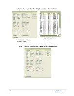
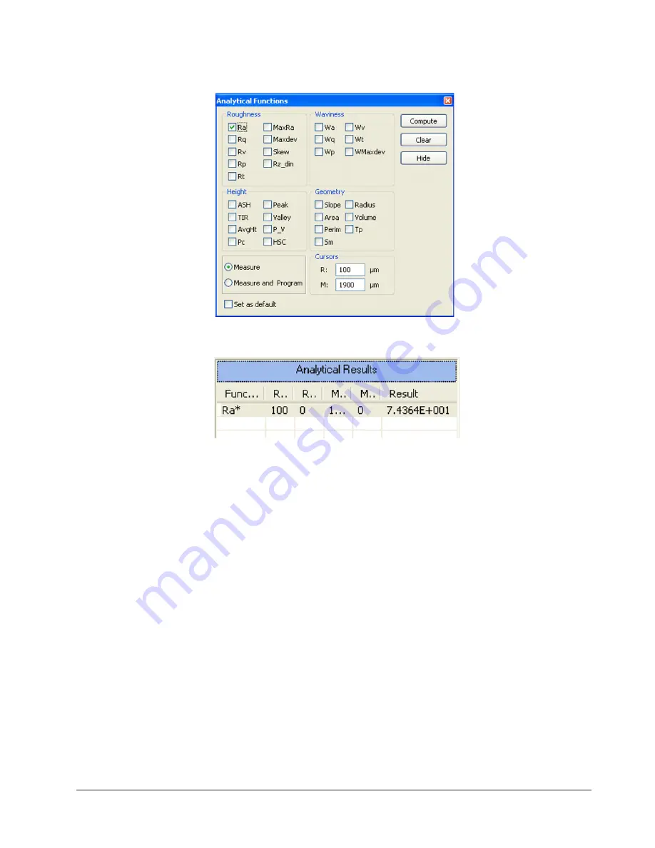
Analytical Functions
Figure 6-8: Compute Ra
Figure 6-9: Analytical Results Display with Ra from Raw Data
DETERMINING THE CUTOFF WAVELENGTH
The Dektak 150 application is equipped with short pass and long pass digital filters for filtering out
high and low frequency signals. The cutoff frequencies define the intended difference between
roughness and waviness.
The filters are designed in accordance with the ANSI B46.1 specification on surface texture. The
wavelengths are user selectable from 1 to 200,000 µm.
The appropriate cutoff wavelength varies from application to application; however, the cut-off
wavelength must be less than the scan length. Also, the cutoff value will not be accepted if fewer than
eight data points are available per cutoff wavelength. The
Scan Resolution
parameter displayed in
the
Scan Routines
window provides the number of µm per sample for a given scan length and speed.
The minimum acceptable cut-off wavelength must be at least eight times longer than the value listed
as the scan resolution. This can be otherwise defined as:
μ
m per sample x 8 = minimum acceptable
cut-off wavelength. For typical applications, the recommended cutoff filter value is 1/5 the scan
length.
For example, the default scan routine used for the purpose of this exercise has a scan length of 2000
μ
m, a scan duration of 1 second and a scan resolution of 0.513 µm per sample. Multiplying 0.513 by
Summary of Contents for Dektak 150
Page 1: ......
Page 7: ......
Page 17: ......
Page 81: ......
Page 105: ......
Page 149: ......
Page 191: ......
Page 251: ......
Page 257: ...A 6 Facilities Specifications Figure A 6 Dektak 150 without Enclosure Side View ...
Page 258: ...Facilities Specifications A 7 Figure A 7 Dektak 150 Dimensions without Enclosure Top View ...
Page 259: ...A 8 Facilities Specifications Figure A 8 Dektak 150 without Enclosure Center of Mass ...
Page 273: ......
Page 283: ......
Page 321: ......
Page 331: ......
Page 333: ......
Page 336: ......
Page 337: ......
Page 349: ......

