Analytical Functions
6-19
routine calculates the new value of each point by looking at the four closest points that lie within the
band.
When the algorithm encounters a point that lies outside the band, the calculation is interrupted. The
new point is left as is and becomes a center point of a new noise band. If the next five points are
within the new band, the calculation restarts. If subsequent points lie outside the band, they are
plotted as is, and each becomes a new reference point.
This technique is preferable to straight filtering, since the slope of the profile is maintained.
Activating the Smoothing Function
You can perform smoothing on profile data at the conclusion of a scan. The procedure for activating
the smoothing function from the
Data Plot
window is described below.
1
Select
Window
>
Data Plot
to display the
Data Plot
window with the replotted profile data.
2
Select
Analysis
>
Analytical Functions
to display the
Analytical Functions
dialog box.
3
Under
Height
, click
TIR
.
4
Select
Measure
.
5
Click
Compute
.
NOTE –
The total peak-to-valley distance is calculated.
6
Select
Analysis
>
Smoothing
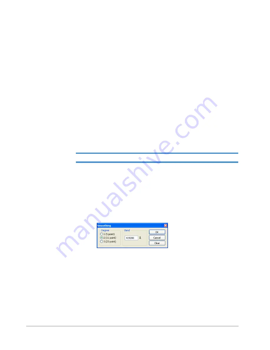
to display a dialog box for entering smoothing parameters (see
7
Select one of three available degrees of smoothing (for the purpose of this exercise, select
2
in the
Degree
section).
8
Enter a value equal to or greater than the value displayed as the
TIR
result in the
Band
field.
9
Click
OK
to smooth and replot the raw profile data.
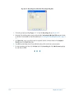
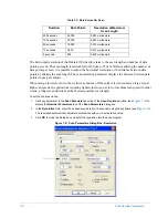
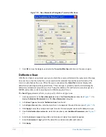
Figure 6-19: Smoothing Dialog Box
Entering Smoothing into a Scan Routine
The following procedure shows you how to enter smoothing into the current scan routine to make it
execute automatically at the conclusion of the scan.
1
Select
Window
>
Scan Routines
to display the
Scan Routines
window.
2
In the
Data Processing
section, click
Smoothing
to display the
Data Processing Parameters
dialog box.
Summary of Contents for Dektak 150
Page 1: ......
Page 7: ......
Page 17: ......
Page 81: ......
Page 105: ......
Page 149: ......
Page 191: ......
Page 251: ......
Page 257: ...A 6 Facilities Specifications Figure A 6 Dektak 150 without Enclosure Side View ...
Page 258: ...Facilities Specifications A 7 Figure A 7 Dektak 150 Dimensions without Enclosure Top View ...
Page 259: ...A 8 Facilities Specifications Figure A 8 Dektak 150 without Enclosure Center of Mass ...
Page 273: ......
Page 283: ......
Page 321: ......
Page 331: ......
Page 333: ......
Page 336: ......
Page 337: ......
Page 349: ......

