Dektak 150 System Overview
1-5
•
A broad line of calibration standards that calibrate the system for any application.
•
A variety of styli for measuring fine surface features and softer samples.
•
The
N
-Lite Low Force Package for using fine tips without damaging the surface.
•
Extended vertical range for measuring large steps or curved surfaces.
•
Scan-stitching software enables shape measurements on samples greater than 55 mm.
•
Stress Measurement for calculating tensile or comprehensive stress on processed wafers.
•
Wyko Vision analysis software (standard with the Y auto stage) that enables true 3D-mapping,
bearing ratio, and over 200 additional analyses.
•
Cantilever deflection for accurate force-over-time measurement.
For a full list of options and accessories, see
Appendix B, Technical Specifications and Purchased
.
HOW THE SYSTEM WORKS
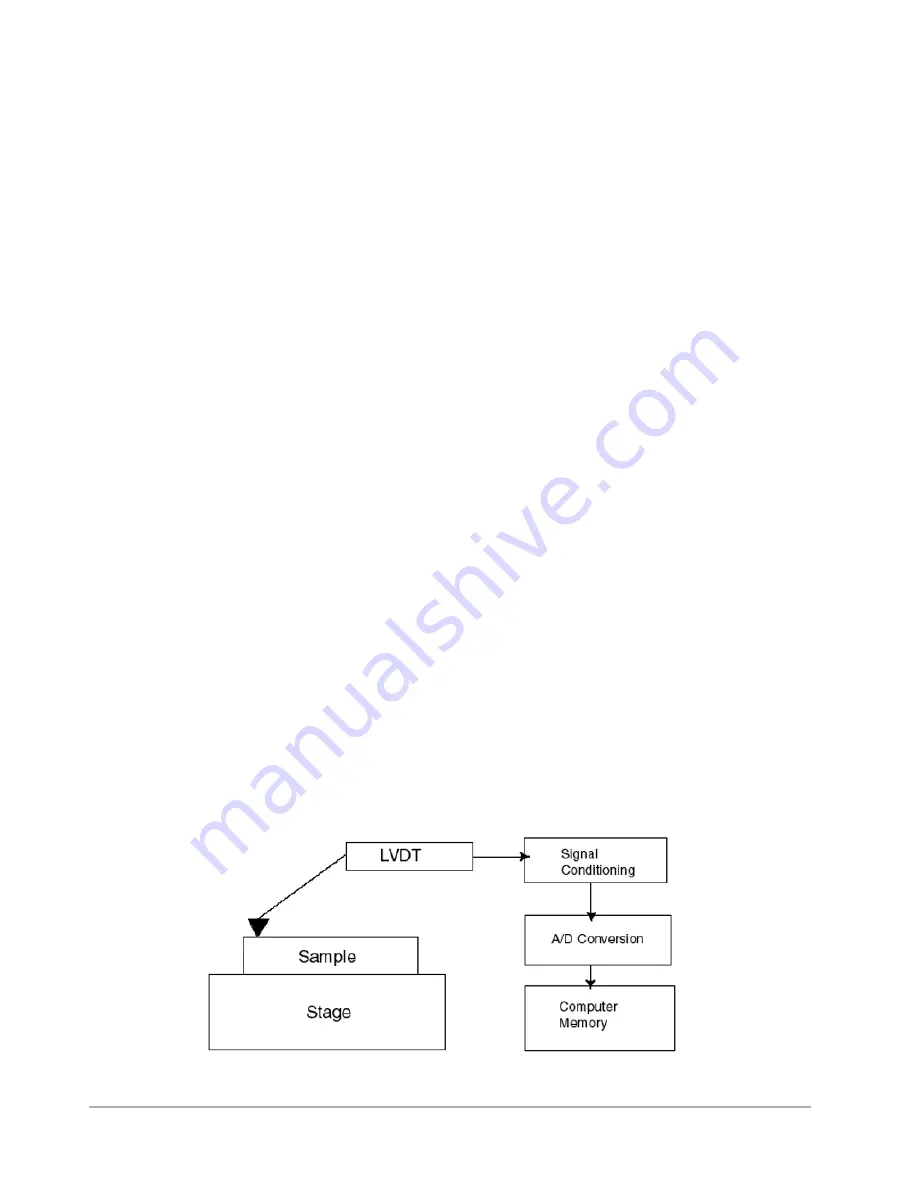
The Dektak 150 profiler takes measurements electromechanically by moving the sample beneath a
diamond-tipped stylus. The high-precision stage moves a sample beneath the stylus according to a
user-programmed scan length, speed and stylus force. The stylus is mechanically coupled to the core
of an LVDT (Linear Variable Differential Transformer).
As the stage moves the sample, the stylus rides over the sample surface. Surface variations cause the
stylus to be translated vertically. Electrical signals corresponding to stylus movement are produced as
the core position of the LVDT changes. The LVDT scales an AC reference signal proportional to the
position change, which in turn is conditioned and converted to a digital format through a high
precision, integrating, analog-to-digital converter.
The digitized signals from performing a single scan are stored in computer memory for display,
manipulation, measurement, and printing. The Dektak 150 stores programs that can easily be
changed to suit both production and laboratory use.
Figure 1-5: Block Diagram of the Dektak 150 Architecture
Summary of Contents for Dektak 150
Page 1: ......
Page 7: ......
Page 17: ......
Page 81: ......
Page 105: ......
Page 149: ......
Page 191: ......
Page 251: ......
Page 257: ...A 6 Facilities Specifications Figure A 6 Dektak 150 without Enclosure Side View ...
Page 258: ...Facilities Specifications A 7 Figure A 7 Dektak 150 Dimensions without Enclosure Top View ...
Page 259: ...A 8 Facilities Specifications Figure A 8 Dektak 150 without Enclosure Center of Mass ...
Page 273: ......
Page 283: ......
Page 321: ......
Page 331: ......
Page 333: ......
Page 336: ......
Page 337: ......
Page 349: ......


